Table of Contents
Ring Counter
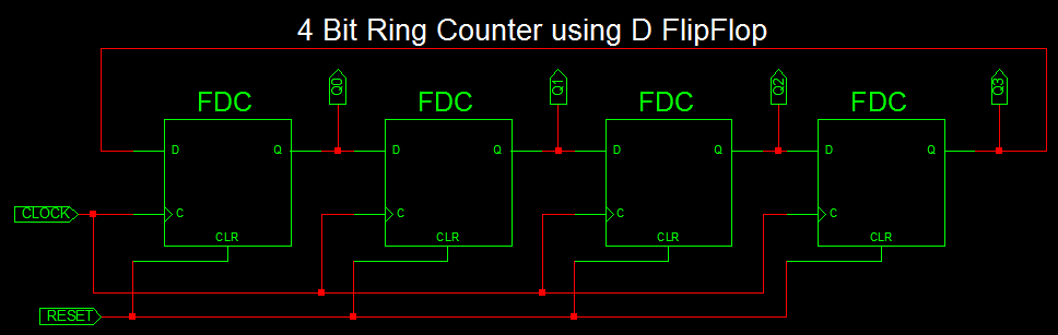
Ring Counter very similar to shift register. At each clock pulse, data at each flipflop shifted to next flipflop with last output is feed back to the input of first flipflop. Also the first flop is set to ‘1’ at the reset state. so it shift bit ‘1’ to next flipflop for each clock input and repeat the sequence as shown below.
4-bit Ring Counter using D FlipFlop

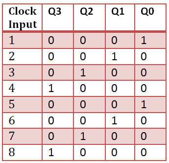
Ring Counter Truth Table
VHDL Code for 4 bit Ring Counter
library IEEE;
use IEEE.STD_LOGIC_1164.ALL;

entity Ring_counter is
    Port ( CLOCK : in  STD_LOGIC;
           RESET : in  STD_LOGIC;
           Q : out  STD_LOGIC_VECTOR (3 downto 0));
end Ring_counter;

architecture Behavioral of Ring_counter is
signal q_tmp: std_logic_vector(3 downto 0):= "0000";
begin
process(CLOCK,RESET)
begin
if RESET = '1' then
	q_tmp <= "0001";
elsif Rising_edge(CLOCK) then
	q_tmp(1) <= q_tmp(0);
	q_tmp(2) <= q_tmp(1);
	q_tmp(3) <= q_tmp(2);
	q_tmp(0) <= q_tmp(3);
end if;
end process;
Q <= q_tmp;
end Behavioral;
VHDL Testbench for 4 bit ring counter
LIBRARY ieee;
USE ieee.std_logic_1164.ALL;

ENTITY Tb_ring_counter IS
END Tb_ring_counter;

ARCHITECTURE behavior OF Tb_ring_counter IS

    -- Component Declaration for the Unit Under Test (UUT)

    COMPONENT Ring_counter
    PORT(
         CLOCK : IN  std_logic;
         RESET : IN  std_logic;
         Q : OUT  std_logic_vector(3 downto 0)
        );
    END COMPONENT;


   --Inputs
   signal CLOCK : std_logic := '0';
   signal RESET : std_logic := '0';

 	--Outputs
   signal Q : std_logic_vector(3 downto 0);

   -- Clock period definitions
   constant CLOCK_period : time := 20 ns;

BEGIN

	-- Instantiate the Unit Under Test (UUT)
   uut: Ring_counter PORT MAP (
          CLOCK => CLOCK,
          RESET => RESET,
          Q => Q
        );

   -- Clock process definitions
   CLOCK_process :process
   begin
		CLOCK <= '0';
		wait for CLOCK_period/2;
		CLOCK <= '1';
		wait for CLOCK_period/2;
   end process;


   -- Stimulus process
   stim_proc: process
   begin
      -- hold reset state for 100 ns.
      wait for 100 ns;

		Reset <= '1';

      wait for 100 ns;

		Reset <= '0';

      wait;
   end process;

END;
VHDL Testbench waveform for 4 bit ring counter
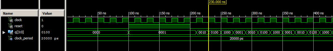
In the waverform, The output value changes as 0001, 0010, 0100, 1000 and repeat the same sequence at the each clock cycle.
Johnson Counter
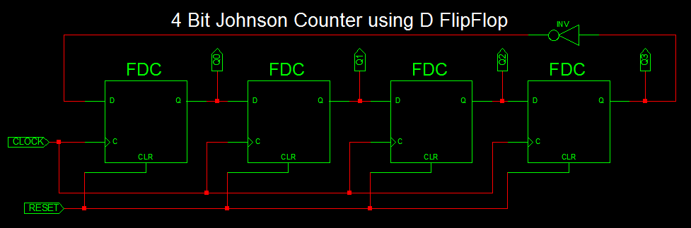
Johnson Counter is also a type of ring counter with output of each flipflop is connected to next flipflop input except at the last flipflop, the output is inverted and connected back to the first flipflop as shown below.
4-bit Johnson Counter using D FlipFlop
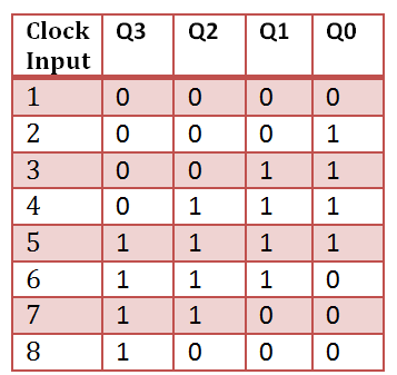
Johnson Counter Truth Table
VHDL Code for 4 bit Johnson Counter
library IEEE;
use IEEE.STD_LOGIC_1164.ALL;

entity Johnson_counter is
Port ( clk : in STD_LOGIC;
rst : in STD_LOGIC;
Q : out STD_LOGIC_VECTOR (3 downto 0));
end Johnson_counter;

architecture Behavioral of Johnson_counter is
signal temp: std_logic_vector(3 downto 0):= "0000";
begin
process(clk,rst)
begin
if rst = '1' then
temp <= "0000";
elsif Rising_edge(clk) then
temp(1) <= temp(0);
temp(2) <= temp(1);
temp(3) <= temp(2);
temp(0) <= not temp(3);
end if;
end process;
Q <= temp;
end Behavioral;
VHDL Testbench for 4 bit Johnson Counter
LIBRARY ieee;
USE ieee.std_logic_1164.ALL;

ENTITY Tb_Johnson_counter IS
END Tb_Johnson_counter;

ARCHITECTURE behavior OF Tb_Johnson_counter IS

    -- Component Declaration for the Unit Under Test (UUT)

    COMPONENT Johnson_counter
    PORT(
         clk : IN  std_logic;
         rst : IN  std_logic;
         Q : OUT  std_logic_vector(3 downto 0)
        );
    END COMPONENT;


   --Inputs
   signal clk : std_logic := '0';
   signal rst : std_logic := '0';

 	--Outputs
   signal Q : std_logic_vector(3 downto 0);

   -- Clock period definitions
   constant clk_period : time := 10 ns;

BEGIN

	-- Instantiate the Unit Under Test (UUT)
   uut: Johnson_counter PORT MAP (
          clk => clk,
          rst => rst,
          Q => Q
        );

   -- Clock process definitions
   clk_process :process
   begin
		clk <= '0';
		wait for clk_period/2;
		clk <= '1';
		wait for clk_period/2;
   end process;


   -- Stimulus process
   stim_proc: process
   begin
      -- hold reset state for 100 ns.
      wait for 100 ns;

		rst <= '1';

      wait for 100 ns;

		rst <= '0';

      wait;
   end process;

END;
Testbench waveform for 4 bit Johnson Counter
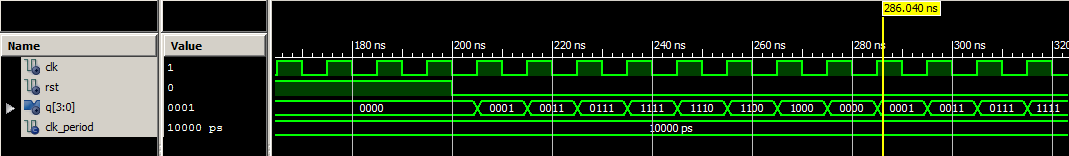
In waveform, the output at the 4th flipflop toggles and outputs johnson counter.