This tutorial explains the step by step procedure to create a ISE project, create source files, synthesize the design, Implement the design and finally verify the functionality in FPGA using the EDGE Spartan 6 board.

Step 1: Open Xilinx ISE design Suite by selecting
Start > All Programs > Xilinx Design Tools > ISE Design Tools 14.7 > ISE Design Suite
or Go to desktop shortcut icon of ISE Design Suite 14.7
Step 2: ISE by default opens the last project otherwise none when open first time.
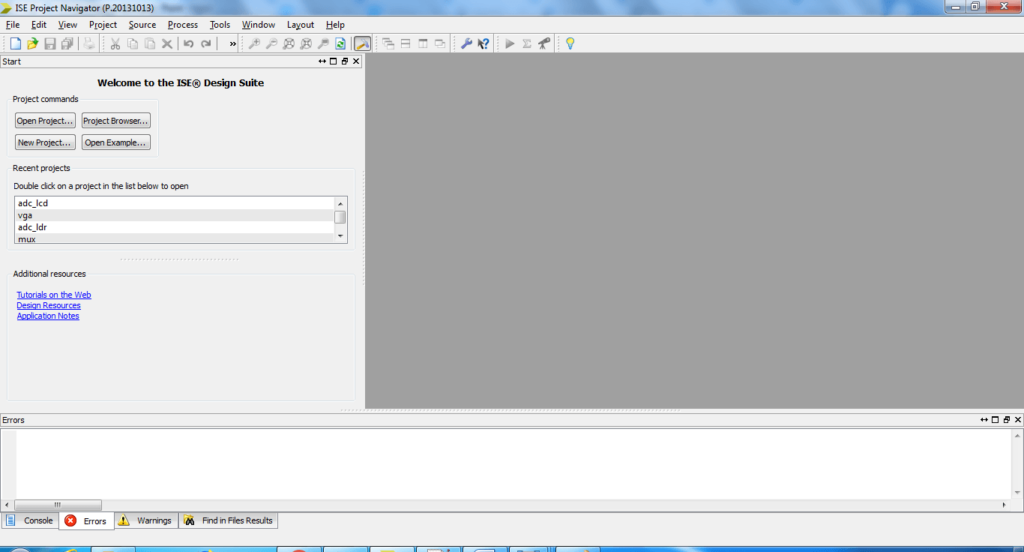
The Design panel (1) contains two windows: Sources window that displays all source files associated with the current design and a Process window that displays all available processes that can be run on a selected source file. The Console panel (2) displays status messages including error and warning messages. The HDL editor window (3) displays source code from files selected in the Design panel.
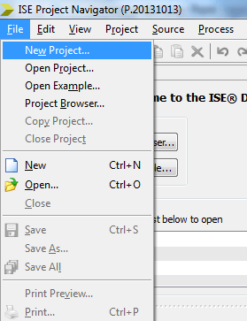
Step 3: Now Create New Project by selecting File > New Project
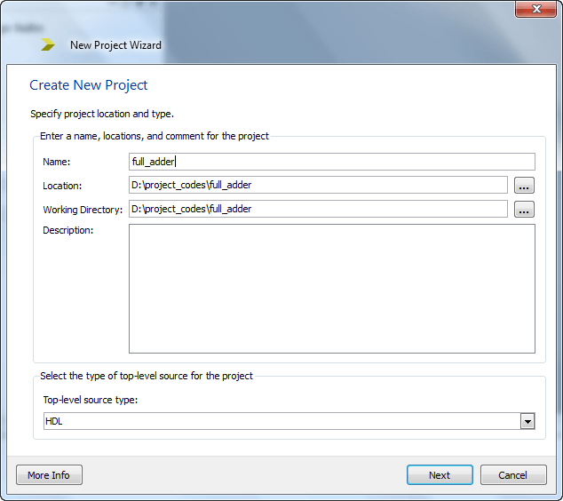
Step 4: Specify Project name and location and click Next
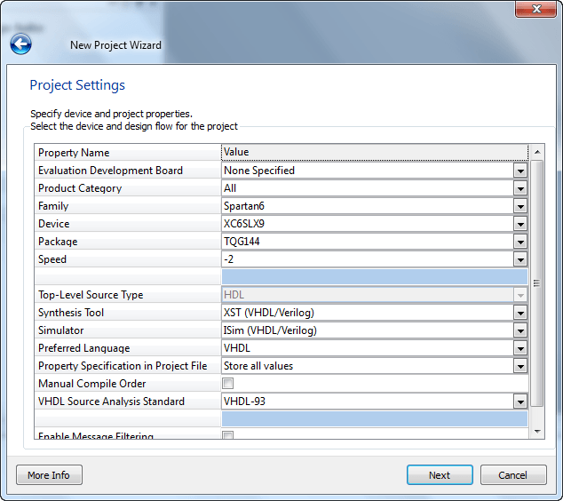
Step 5: Select family, device, package and speed for your project.
Family – Spartan6
Device – XC6SLX9
Package – TQG144
Synthesis Tool – XST(VHDL/VERILOG)
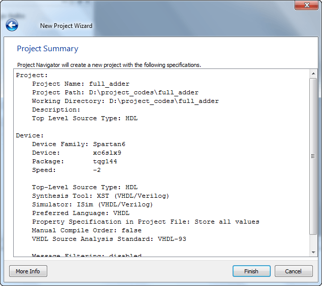
Step 6: Now New Project Wizard displays project summary of the selected specifications for the project. Now Click Finish
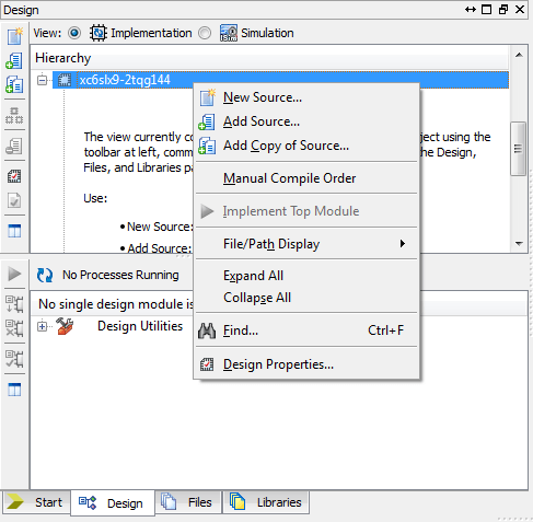
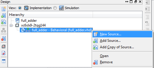
Step 7: ISE opens the project in Project Navigator. To add new source file, Right click on Device name under source window and select New Source.
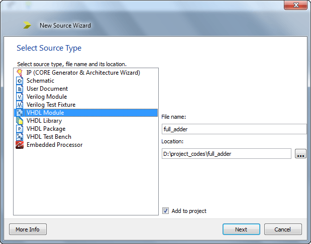
Step 8: Select the VHDL module as a source type. Specify the file name and location
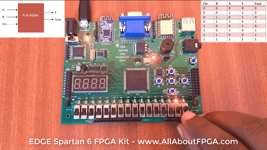
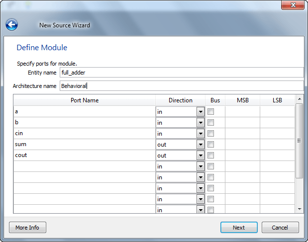
Step 9: Define the Input and Output port details for the VHDL module. Here we have chosen a, b, cin as input ports and sum, carry as output ports. Click Next and then Finish to complete the VHDL source file creation.
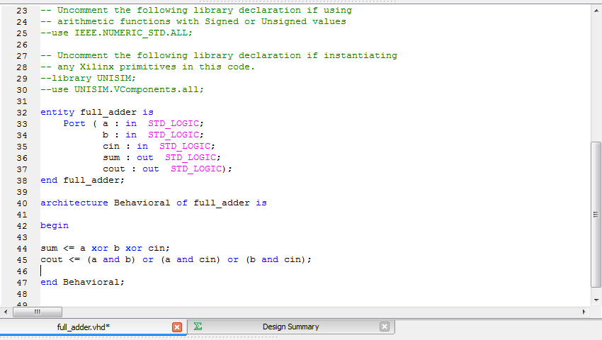
Step 10: After creation of creating new VHDL file. In HDL editor window, you can see entity statement and architecture statement with begin and end statements.
In architecture body you can define various concurrent statement to describe any VHDL circuit. If there are any syntax errors in the source file, the error message will be present in console panel. Finally Save the design file.
library IEEE;
use IEEE.STD_LOGIC_1164.ALL;

entity full_adder is
Port ( a : in STD_LOGIC;
b : in STD_LOGIC;
cin : in STD_LOGIC;
sum : out STD_LOGIC;
cout : out STD_LOGIC);
end full_adder;

architecture Behavioral of full_adder is

begin

sum <= a xor b xor cin;
cout <= (a and b) or (a and cin) or (b and cin);

end Behavioral;
Step 11: The Xilinx tools use a User Constraints File (UCF) to define user constraints like physical pin to circuit net mappings. To create a UCF you have to create a new source file from the hierarchy section
Step 12: This starts the New Source Wizard, which prompts you for the Source type and file name. Select implementation constraint file and specify its name.
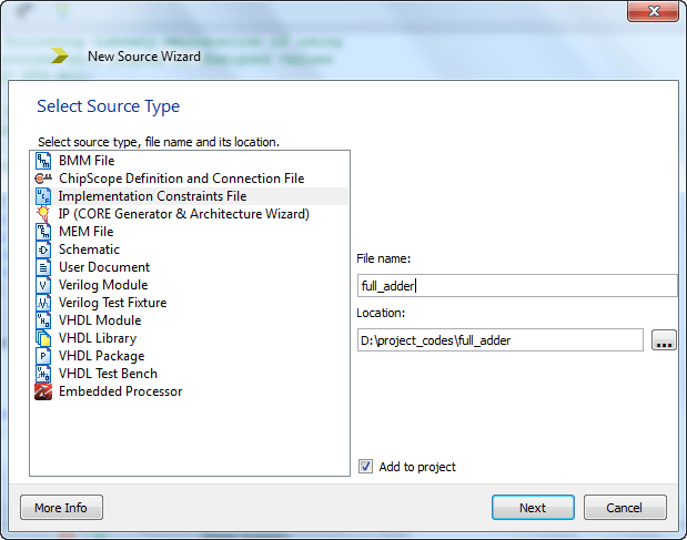
Step 13: Click Next and then Finish to complete the User Constraints file creation.
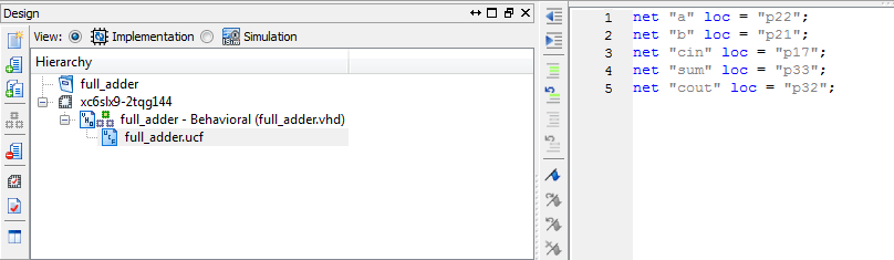
Step 14: NET “portname” LOC =”pin” the three inputs are assigned to switches and the output is assigned to LEDS on the spartan 6 board and Save the UCF file.
net "a" loc = "p22";
net "b" loc = "p21";
net "cin" loc = "p17";
net "sum" loc = "p33";
net "cout" loc = "p32";
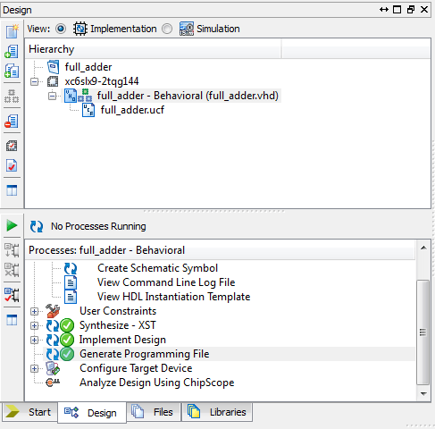
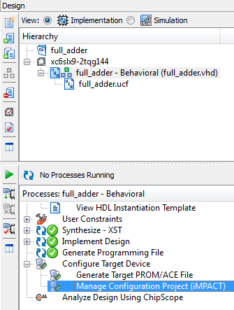
Step 15: Once you have completed VHDL Source file and UCF file creation, perform synthesis, Implementation and generate bitstream by click them one by one in Process window.
Step 16: After Generating Programming File Select Manage Configuration Project to open iMPACT
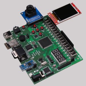
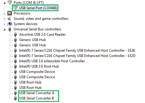
Step 17: Connect EDGE Spartan 6 FPGA Kit to PC through USB cable and Turn On the kit. Open device manager to verify drivers are installed as shown below. Otherwise install USB Programmer drivers by referring kit user manual driver installation section.
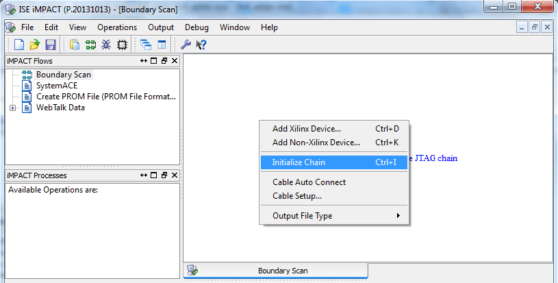
Step 18: Now double click on Boundary scan option and right click on the blank window and select Initialize Chain as shown below
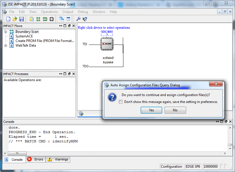
Step 19: Now XC6SLX9 FPGA detected and asking to assign configuration file to it. Click yes
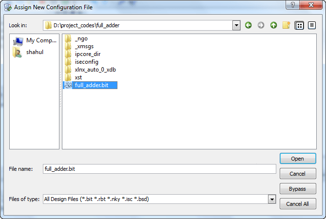
Step 20: Select bit file for full adder from the browse window
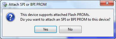
Step21 : Now it ask for PROM device. Skip it by selecting No
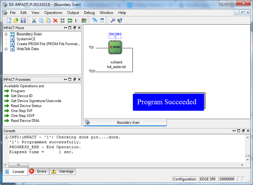
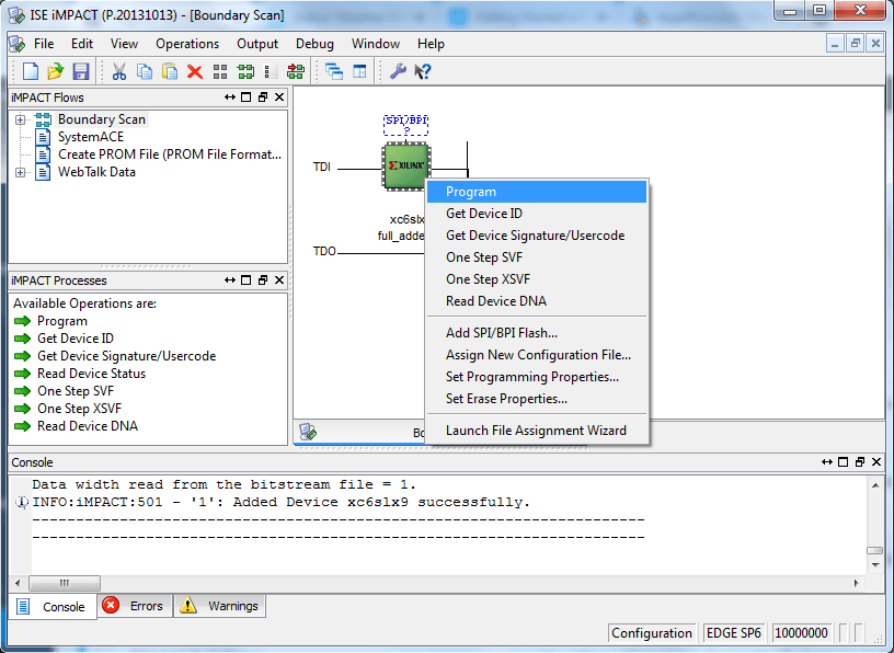
Step 22: Now right click on Spartan6 FPGA and click program.
Step 23: It displays Program Succeeded message and Done LED glow on EDGE Board for the indication of Programming completed.