Table of Contents
Overview
This package of demonstration projects can be used to illustrate the features of the EDGE FPGA development platform. Each chapter of this document will provide a brief overview for a basic demonstration of some of the EDGE Board components and capabilities. In each chapter, there are details of the hardware required, version of Xilinx tools required, included support files and instructions to perform the demonstrations.
The edge_artix7_codes zipped folder contains this manual and directories for each chapter. In each chapter directory there are source files, compiled bit files, and documentation files for any additional hardware used. All projects were developed in Vivado Design Suite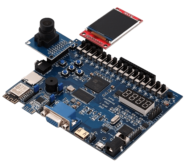
Setting up and programming the EDGE Artix 7 Board
In every chapter, the board will need to be setup and programmed. This section describes how to accomplish this.
Hardware Required:
– EDGE Artix 7 FPGA Development board
– USB A to type B cable
Software Required:
– Vivado Design Suite 2018.1 or latest
Instructions:
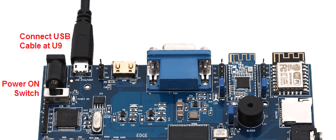
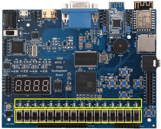
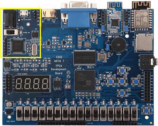
1. Connect the USB A to USB Micro B cable to the USB port (U9) on the EDGE Artix 7 Board above the power switch
2. Change the power switch position from Ext to USB on the EDGE Board to Power ON.
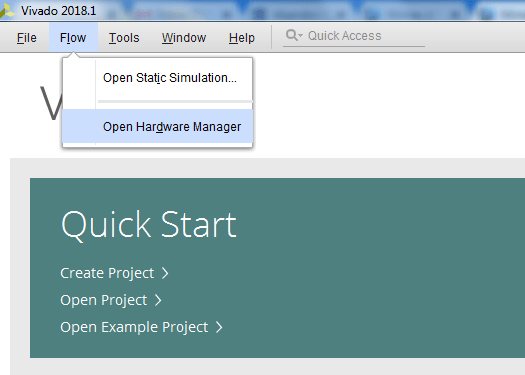
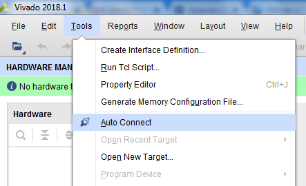
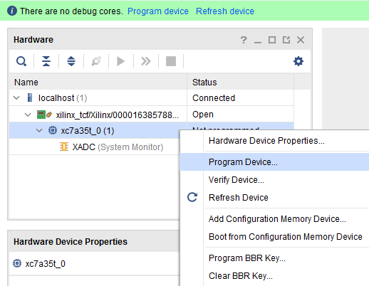
Open Vivado Design Suite and Select “Hardware Manager -> Open Target -> Auto Connect”
If the device is detected successfully, then select “Program Device” by right click on the target device “xc7a35t_0” as shown below
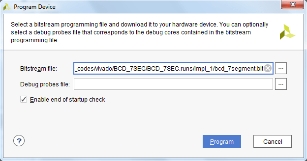
Browse the Bit file need to be downloaded to the Artix 7 FPGA and click Program.
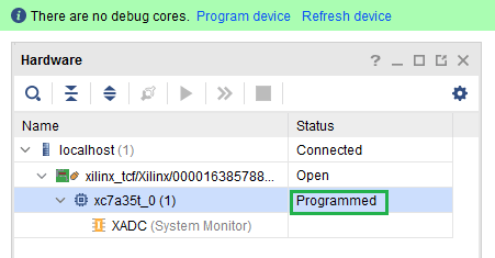
Once the Program Succeeds, Done LED D1 light up on EDGE Artix 7 FPGA kit.
Chapter 1: Switch LED Demo
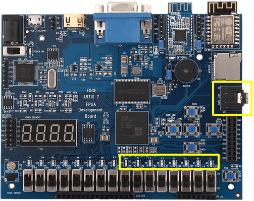
This is a simple demo that changes the status of the user LEDs (D3-D19) when user change SPDT switch state from low to High.
Additional Hardware Required:
None
Software Platforms:
– Vivado Design Suite 2018.1 or latest
Supplied Files:
– Vivado project files
Instructions:
1. Setup and program the board as described in the “Setting up and programming the EDGE Board” Section
The LEDs (D3 – D19) will light, when the SPDT Switches change their state from LOW to High.
Chapter 2: BCD to 7 Segment Demo
This is a simple demo that displays 4 bit Switch BCD state in 7 Segment Display.
Additional Hardware Required:
– none
Software Platforms:
– Vivado Design Suite 2018.1 or latest
Supplied Files:
– Vivado project files
Instructions:
1. Setup and program the board as described in the “Setting up and programming the EDGE Board” Section
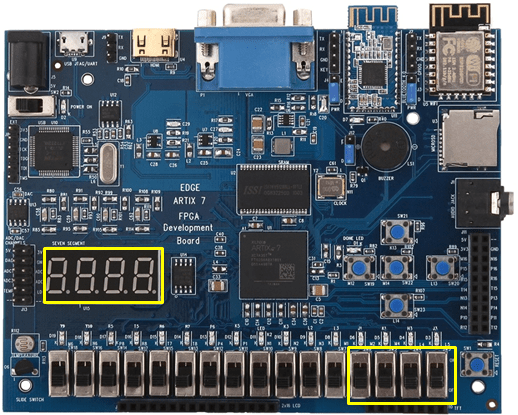
SPDT Switch SW3, SW4, SW5, SW6 is assigned for input of 4 bit BCD value.
When the Switch State is changed from 0000 to 1001 state corresponding decimal value is displayed on the seven segment displays from 0 to 9.
Chapter 3: Seven Segment Display counter demo
This is a simple demo that displays decimal Counter on 7 Segment Display.
Additional Hardware Required:
– none
Software Platforms:
– Vivado Design Suite 2018.1 or latest
Supplied Files:
– Vivado project files
Instructions:
1. Setup and program the board as described in the “Setting up and programming the EDGE Board” Section
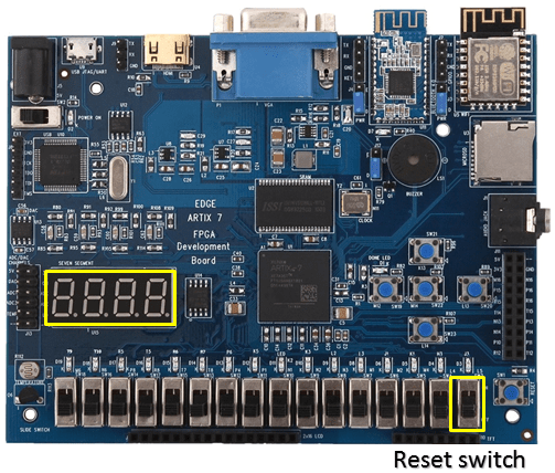
Decimal counter counts from 0 to 9999. The counter increments at the interval of 1 sec and repeat the sequence.
Reset switch sw3 is used to reset the counter to 0.
Chapter 4: Push Button Demo
This is a simple demo display the Push button state on LEDs.
Additional Hardware Required:
None
Software Platforms:
– Vivado Design Suite 2018.1 or latest
Supplied Files:
– Vivado project files
Instructions:
1. Setup and program the board as described in the “Setting up and programming the EDGE Board” Section
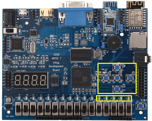
Each of 5 Push Button states is directly assigned to LEDs. When the user press Push Button corresponding LED turn ON. Push Button switch SW19, SW20, SW21, SW22 and SW23 are assigned in this demonstration with respective of LED D3, D4, D5, D6, and D7.
Chapter 5: Buzzer Demo
This is a simple demo produce sound at piezo Buzzer at regular interval.
Additional Hardware Required:
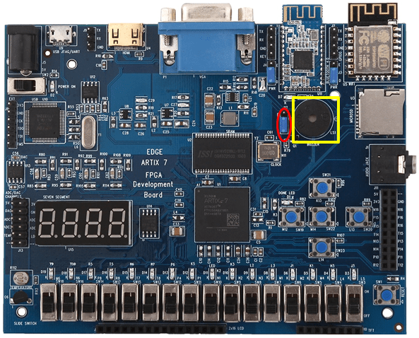
To enable Buzzer, Jumper needs to be placed at Enable position at J6
Software Platforms:
– Vivado Design Suite 2018.1 or latest
Supplied Files:
– Vivado project files
Instructions:
1. Setup and program the board as described in the “Setting up and programming the EDGE Board” Section
PWM pulse of 2 sec is generated and supplied to buzzer.
5v Piezo buzzer produce beep sound at the interval of 2 sec.
Chapter 6: 2×16 LCD Demo
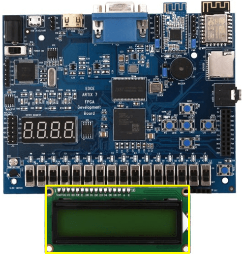
This is a simple demo for displaying characters in the 2×16 LCD.
Additional Hardware Required:
Connect 2×16 LCD display at J7 Header
Software Platforms:
– Vivado Design Suite 2018.1
Supplied Files:
– Vivado project files
Instructions:
1. Setup and program the board as described in the “Setting up and programming the EDGE Board” Section
2×16 LCD displays the following characters 123456789ABCDEF in the second row.
Chapter 7: Temperature Sensor and LDR (ADC) Demo
This demo reads the temperature and light intensity value through XADC and displays it on LCD.
Additional Hardware Required:
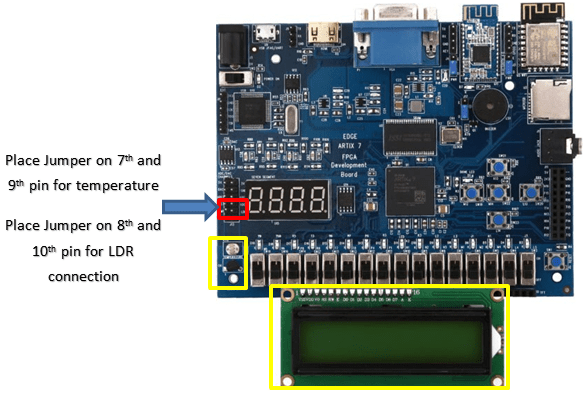
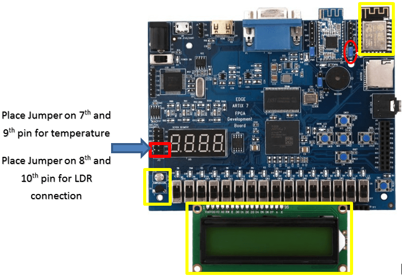
Connect 2×16 LCD display at J7 Header.
External Temperature Sensor LM35 Input is available at the 9th pin of ADC Connector. To Connect Temperature sensor with XADC, Place a jumper between 7th and 9th pin of J13 Connector.
LDR input is available at the 10th pin of ADC Connector. To Connect LDR sensor with XADC, Place a jumper between 8th and 10th pin of ADC Connector.
Software Platforms:
– Vivado Design Suite 2018.1 or latest
Supplied Files:
– Vivado project files
Instructions:
1. Setup and program the board as described in the “Setting up and programming the EDGE Board” Section
Temperature input at channel 7 of XADC is converted to 16 bit digital output. LDR input at channel 15 of XADC is converted to 16 bit digital output.
Both temperature sensor and LDR outputs are displayed in 2×16 LCD. By placing finger over the top of Temperature sensor or LDR, Variation can be easily verified on LCD.
Chapter 8: UART Demo
This demo transmit the ASCII data through UART at 9600 baud Rate.
Additional Hardware Required:
-none
Software Platforms:
– Vivado Design Suite 2018.1 or latest
Supplied Files:
– Vivado project files
Instructions:
1. Setup and program the board as described in the “Setting up and programming the EDGE Board” Section
UART interface is transmitting at the max baud rate of 3 M Baud.
We are transmitting ASCII data Hello World at 9600 Baud rate.
Chapter 9: DAC Demo
This demo output the sine wave generated from DAC IC
Additional Hardware Required:
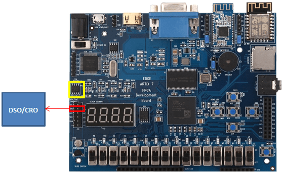
Connect DSO probe at 19th and 20th pin of J3 connector to view the Analog output.
Software Platforms:
– Vivado Design Suite 2018.1 or latest
Supplied Files:
– Vivado project files
Instructions:
1. Setup and program the board as described in the “Setting up and programming the EDGE Board” Section
MCP4921 SPI DAC IC converts 12 bit digital discrete sign Values to continuous analog sine wave Output at the connector J13.
Connect DSO at 19th and 20th pin of J3 connector to view the Analog output.
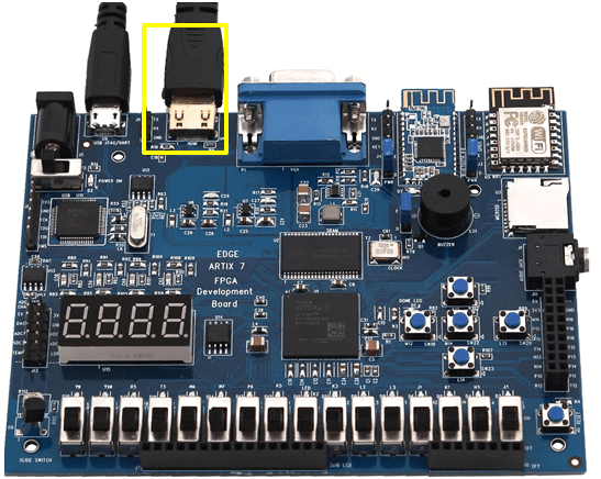
Chapter 10: HDMI /DVI-D Demo
This demo displays a 480p colour screen using DVI-D / HDMI Monitor.
Additional Hardware Required:
Connect HDMI cable at the U4 Connector and connect the other end to HMDI monitor
Software Platforms:
– Vivado Design Suite 2018.1 or latest
Supplied Files:
– Vivado project files
Instructions:
1. Setup and program the board as described in the “Setting up and programming the EDGE Board” Section
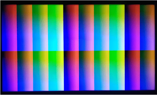
HDMI port work with 640*480 frame which is actually sent as an 800*525 frame.
It specifies a 25MHz minimum pixel clock. It has three 4 bit primary colours such as red, green, blue
Display of HDMI monitor:
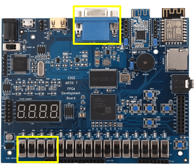
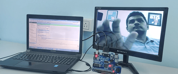
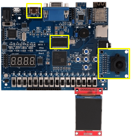
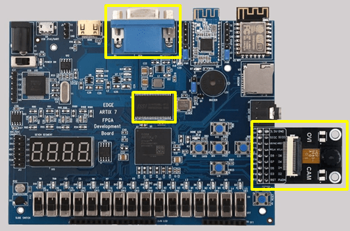
Chapter 11: Image processing Demo
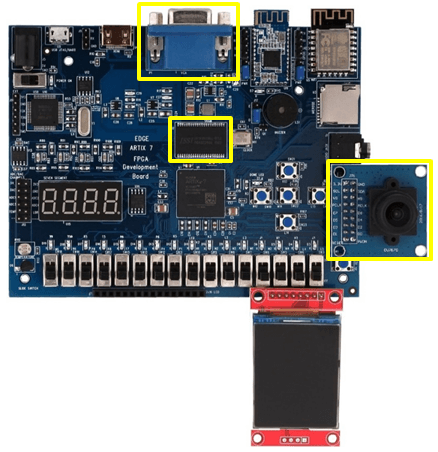
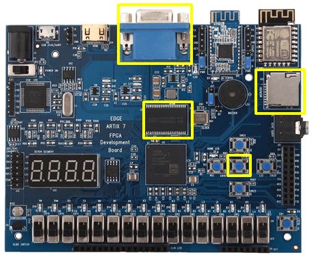
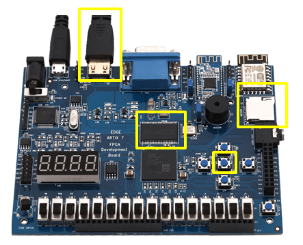
This demo displays the OV7670 CMOS Camera sensor output in the VGA Monitor as a video frames.
Additional Hardware Required:
Connect VGA Monitor to the connector P1
Software Platforms:
– Vivado Design Suite 2018.1 or latest
Supplied Files:
– Vivado project files
Instructions:
Setup and program the board as described in the “Setting up and programming the EDGE Board” Section
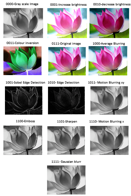
The image converted into flower.coe file for storing the image in FPGA BRAM
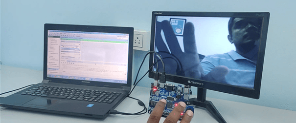
According to the switch input shown below, the system process the image and display the result on a VGA monitor.
| SWITCH INPUT | IMAGE OUTPUT |
| 0000 | RGB image to Gray scale image |
| 0001 | Increase brightness |
| 0010 | Decrease brightness |
| 0011 | colour inversion |
| 0111 | original image |
| 1000 | average blurring |
| 1001 | sobel edge detection |
| 1010 | edge detection |
| 1011 | motion blurring xy |
| 1100 | emboss |
| 1101 | sharpen |
| 1110 | motion blur x |
| 1111 | Gaussian Blur |
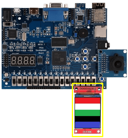
Chapter 12a: SPI TFT Display – colour band Demo
This demo displays the colour band on the SPI TFT Display.
Additional Hardware Required:
Connect SPI TFT to the connector J10
Software Platforms:
– Vivado Design Suite 2018.1 or latest
Supplied Files:
– Vivado project file
Instructions:
Setup and program the board as described in the “Setting up and programming the EDGE Board” Section
1.8 inch SPI TFT Display the pixel area of 128×160.
Color band data is sent to TFT Display through SPI Protocol.
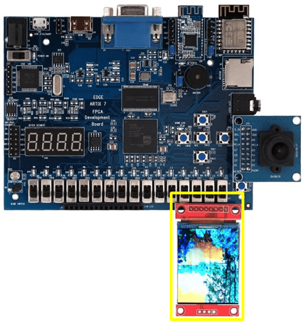
Chapter 12b: SPI TFT Display – colour image Demo
This demo displays the 128 x 160 pixel colour image on the SPI TFT Display.
Additional Hardware Required:
Connect SPI TFT to the connector J10
Software Platforms:
– Vivado Design Suite 2018.1 or latest
Supplied Files:
– Vivado project file
Instructions:
Setup and program the board as described in the “Setting up and programming the EDGE Board” Section
1.8 inch SPI TFT Display the pixel area of 128×160.
The image converted into image.coe file for storing the image in FPGA BRAM
Through SPI Protocol image is transferred from BRAM to SPI TFT display as shown below
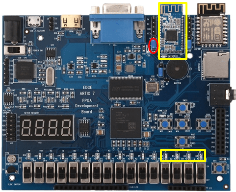
Chapter 13: Bluetooth Demo
In this demo, FPGA LEDs are controlled through Bluetooth interface.
Additional Hardware Required:
To enable power supply to the Bluetooth modem place jumper at Enable and centre pin of J4.
D19 LED ON/OFF at every 1 sec delay to represent Bluetooth is ready to pair.
Software Platforms:
– Vivado Design Suite 2018.1 or latest
Supplied Files:
– Vivado Project file
Instructions:
1. Setup and program the board as described in the “Setting up and programming the EDGE Board” Section
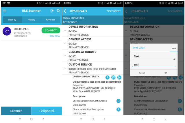
We are going to control On-board LEDs through Bluetooth via Android Phone App.
Install BLE Scanner App from play store. Pair with Bluetooth device on FPGA kit. D7 LED glow continuously once paired with Bluetooth.
Under Custom Services, select W option to send some data through Bluetooth. EDGE Board LEDs D2, D3, D4 and D5 are turned ON sending 1, 3, 5, and 7 respectively through Bluetooth.
Those LEDs are turned OFF by sending 2, 4, 6, and 8 through Bluetooth.
Chapter 14: Wi-Fi Demo
In this demo, Temperature and LDR data is sent to cloud through Wi-Fi Interface.
Additional Hardware Required:
To enable power to the WiFi device, Place jumper at E and centre pin of J3.
Connect 2×16 LCD display at J7 Header.
External Temperature Sensor LM35 Input is available at the 9th pin of ADC Connector. To Connect Temperature sensor with XADC, Place a jumper between 7th and 9th pin of J13 Connector.
LDR input is available at the 10th pin of ADC Connector. To Connect LDR sensor with XADC, Place a jumper between 8th and 10th pin of ADC Connector.
Software Platforms:
– Vivado Design Suite 2018.1 or latest
Supplied Files:
– Vivado Design Suite
Instructions:
1. Setup and program the board as described in the “Setting up and programming the EDGE Board” Section
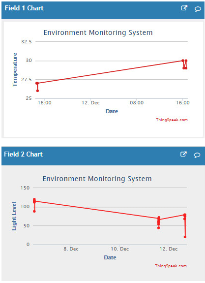
Monitoring Temperature data through IoT
Transmitting Temperature and light level data through WiFi involves communication with cloud server using IP Address. We used an open source data logger website thingspeak.com to reduce the implementation cost. It provides a free user space for creating the data channels. Each channel will be having 8 fields to write the various data and it automatically plots the given data in a graphical representation.
We have to program for ESP8266-12F to send the required AT commands and to establish a connection between the system and thingspeak server.
Once we created our channel for entering the data into cloud, the channel will be allocated with one API key. So we have to write the API key before writing the actual data, then the data will be stored and displayed in the required channel.
We have created two thingspeak channel that includes field 1 for Temperature Reading and field 2 for light level reading. The actual data obtained from the sensor will be first stored in a script and then the thingspeak server will automatically plots the data retrieving from the field.
To access the data from personal computing devices such Laptop, Tablet and Mobile Phone channel ID is required. Channel ID will be provided by Thingspeak.com when you create new channel. These channel ID can be changed to private or public depending on the application requirement.
Example Channel ID Will be like
https://thingspeak.com/channels/384072
Procedure to check the IoT Demo Code
Step 1: To start using ThingSpeak, you must create a new MathWorks account.
https://thingspeak.com/users/sign_up
Step 2: Login and setting up new channel to collect and display temperature data.
https://www.mathworks.com/help/thingspeak/collect-data-in-a-new-channel.html
New channel created can be available to the public or private based on settings selected.
Step 3: Establishing connection between ESP12F WiFi modem and Thingspeak cloud. We have send the following AT commands.
AT+RST
Reset the WiFi Module to Default State
AT+CWJAP=”WIFINAME”,”Password”
Set the home/office Wifi User Id and Password to connect ESP module to the internet
AT+CIPSTART=”TCP”,”184.106.153.149″,80
Connecting to TCT IP Address of Thingspeak.com
AT+CIPSEND=49
Sending total lengh of the data to transmitted to server.
GET /update?api_key=XXXXXXXXXXXXXXXX&field1=000
Set your API key received when creating new channel. Field 1 represent temperature value and Field 2 represent light intensity value.
AT+CLOSE
Close the communication with server.
Step 4: After updating IoT project file with WiFi user id, password and API key. Regenerate the project and download the bit file to FPGA.
Note: WiFi user id and password length may vary. We need to update the array length based on it.
Step5: Monitoring the data through channel id.
https://thingspeak.com/channels/384072
With API key and channel id, we can also monitor the output in Android / IOS App.
Chapter 15: Audio Demo
This demo generates 2-voice music box that plays J.S. Bach’s Invention at audio connector
Additional Hardware Required:
Connect head phone jack or speaker to the stereo Audio Connector
Software Platforms:
– Vivado Design Suite 2018.1 or latest
Supplied Files:
– Vivado Project file
Instructions:
1. Setup and program the board as described in the “Setting up and programming the EDGE Board” Section
Stereo Audio tempo is displayed on the LEDs.
Music is held in a BRAM-based ROM, as are the tone frequencies (well-tempered scale), and output waveform. Output is 12-bit PWM at 48 KHz on each of the two audio outputs. This music conveniently has only two voices and one is played on each channel (left or right).
The music is repeating again and again.
Chapter 16a: OV7670 SDRAM VGA Demo
In this demo, OV7670 CMOS Camera data, store it in SDRAM and display on the VGA Monitor
Additional Hardware Required:
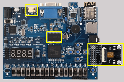
To interface OV7670 CMOS Camera with the Board, Leave pin1 and pin2 unconnected. Connect pin3 of expansion connector to pin1 of CMOS Camera.
Connect VGA monitor to FPGA kit
Software Platforms:
– Vivado Design Suite 2018.1 or latest
Supplied Files:
– Vivado Project file
Instructions:
Connect OV7670 camera module and VGA monitor to the FPGA kit, retrieve video frames from the camera module, store temporarily each image frame’s data inside the SDRAM, and use that data to drive a VGA monitor connected to the board.
Chapter 16b: OV7670 SDRAM HDMI Demo
In this demo, OV7670 CMOS Camera data, store it in SDRAM and display on the HDMI Monitor
Additional Hardware Required:
To interface OV7670 CMOS Camera with the Board, Leave pin1 and pin2 unconnected. Connect pin3 of expansion connector to pin1 of CMOS Camera.
Connect HDMI monitor to FPGA kit
Software Platforms:
– Vivado Design Suite 2018.1 or latest
Supplied Files:
– Vivado Project file
Instructions:
Connect OV7670 camera module and HDMI monitor to the FPGA kit, retrieve video frames from the camera module, store temporarily each image frame’s data inside the SDRAM, and use that data to drive a HDMI monitor connected to the board.
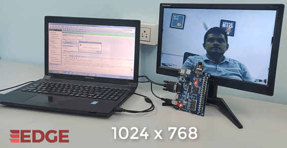
Chapter 17a: OV5640 SDRAM VGA Demo
In this demo, OV5640 CMOS Camera data, store it in SDRAM and display on the VGA Monitor
Additional Hardware Required:
To interface OV5640 CMOS Camera with the Board, Leave pin1 and pin2 unconnected. Connect pin3 of expansion connector to pin1 of CMOS Camera.
Connect VGA monitor to FPGA kit
Software Platforms:
– Vivado Design Suite 2018.1 or latest
Supplied Files:
– Vivado Project file
Instructions:
Connect OV5640 camera module and VGA monitor to the FPGA kit, retrieve video frames from the camera module, store temporarily each image frame’s data inside the SDRAM, and use that data to drive a VGA monitor connected to the board.
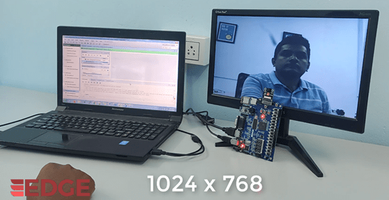
Chapter 17b: OV5640 SDRAM HDMI Demo
In this demo, OV5640 CMOS Camera data, store it in SDRAM and display on the HDMI Monitor
Additional Hardware Required:
To interface OV5640 CMOS Camera with the Board, Leave pin1 and pin2 unconnected. Connect pin3 of expansion connector to pin1 of CMOS Camera.
Connect HDMI monitor to FPGA kit
Software Platforms:
– Vivado Design Suite 2018.1 or latest
Supplied Files:
– Vivado Project file
Instructions:
Connect OV5640 camera module and HDMI monitor to the FPGA kit, retrieve video frames from the camera module, store temporarily each image frame’s data inside the SDRAM, and use that data to drive a HDMI monitor connected to the board.
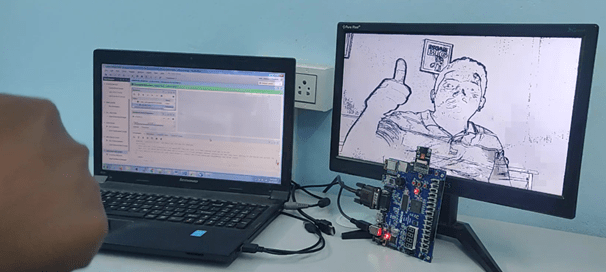
Chapter 17c: OV5640 SDRAM VGA edge detection Demo
In this demo, OV5640 CMOS Camera data, store it in SDRAM and display edge detection video processing on the VGA Monitor
Additional Hardware Required:
To interface OV5640 CMOS Camera with the Board, Leave pin1 and pin2 unconnected. Connect pin3 of expansion connector to pin1 of CMOS Camera.
Connect VGA monitor to FPGA kit
Software Platforms:
– Vivado Design Suite 2018.1 or latest
Supplied Files:
– Vivado Project file
Instructions:
Connect OV5640 camera module and VGA monitor to the FPGA kit, retrieve video frames from the camera module, store temporarily each image frame’s data inside the SDRAM, use that data to perform edge detection algorithm and display it on VGA monitor connected to the board.
Chapter 18a: SD Card SDRAM VGA Demo
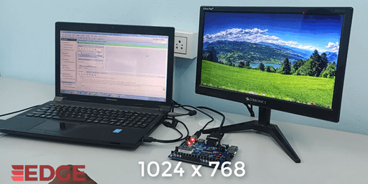
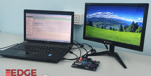
The demo is to read a BMP image of SD card, store in SDRAM and display it on a screen through a VGA port
Additional Hardware Required:
Insert the microSD card into the microSD port
Connect VGA Monitor
Software Platforms:
– Vivado Design Suite 2018.1 or latest
Supplied Files:
– Vivado Project file
Instructions:
Setup and program the board as described in the “Setting up and programming the EDGE Board” Section
Copy bmp image as 1.bmp, 2.bmp with a resolution of 1024×768 to MicroSD card.
Insert to SD card slot in the board and connect VGA monitor.
Use centre push button SW22 to switch the image read.
Output Image Displaying on the VGA Monitor
Chapter 18b: SD Card SDRAM HDMI Demo
The demo is to read a BMP image of SD card, store in SDRAM and display it on a screen through a HDMI port
Additional Hardware Required:
Insert the microSD card into the microSD port
Connect HDMI Monitor
Software Platforms:
– Vivado Design Suite 2018.1 or latest
Supplied Files:
– Vivado Project file
Instructions:
Setup and program the board as described in the “Setting up and programming the EDGE Board” Section
Copy bmp image as 1.bmp, 2.bmp with a resolution of 1024×768 to MicroSD card.
Insert to SD card slot in the board and connect HDMI monitor.
Use centre push button SW22 to switch the image read.
Output Image Displaying on the HDMI Monitor
-
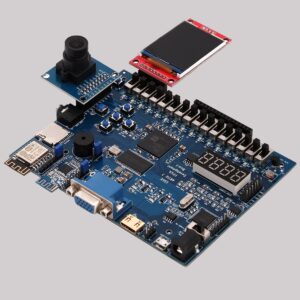 EDGE Artix 7 FPGA Development Board₹ 13,750