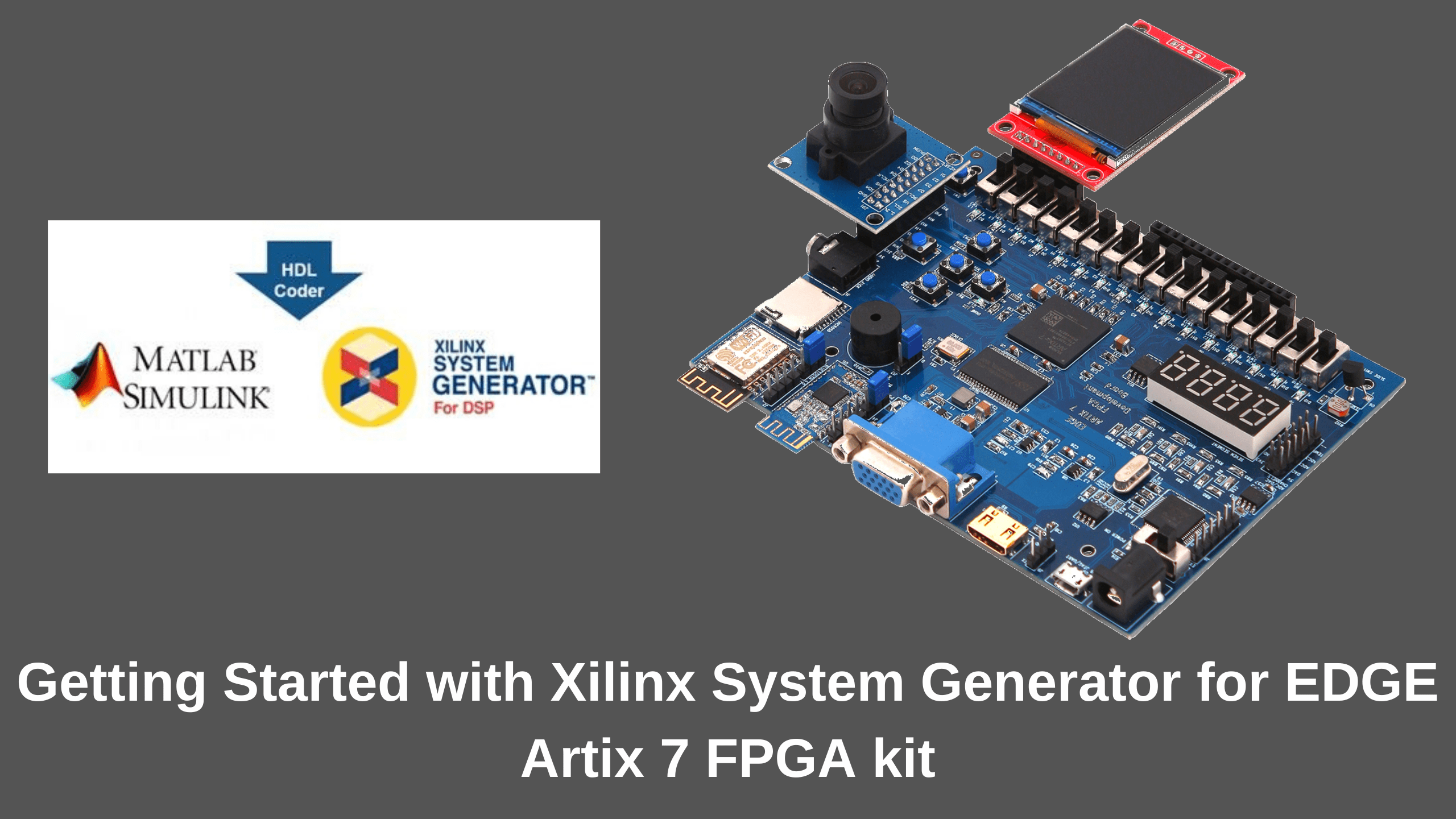
System Generator is a powerful tool that integrates Xilinx FPGA design process with MATLAB’s Simulink which uses a high-level description to easily realize a complex system. We first design the system and verify its functionality in the Simulink environment. The graphical high-level description of Simulink significantly facilitates modeling, simulating, and analyzing the design. Then, we can generate the VHDL description of the design and add it to our project in the Vivado design suite software.
Prerequisites
Before launching the System Generator, you should note two points:
- Make sure that your System Generator version is compatible with the MATLAB version that you’re going to use. Here, we have used MATLAB 2018a and Vivado 2018.1
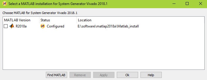
- Configure the MATLAB software with your System Generator by selecting
Start > All Programs > Xilinx Design Tools > Vivado 2018.1 >System generator >System generator 2018.1 MATLAB configurator
Starting the System Generator
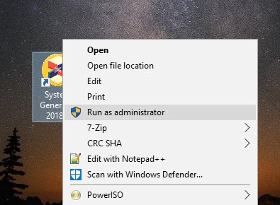
Step 1: Start the System generator with Run as administrator by choosing
Start > All Programs > Xilinx Design Tools > System Generator\Sysgen Generator or
Select the System generator in desktop shortcut
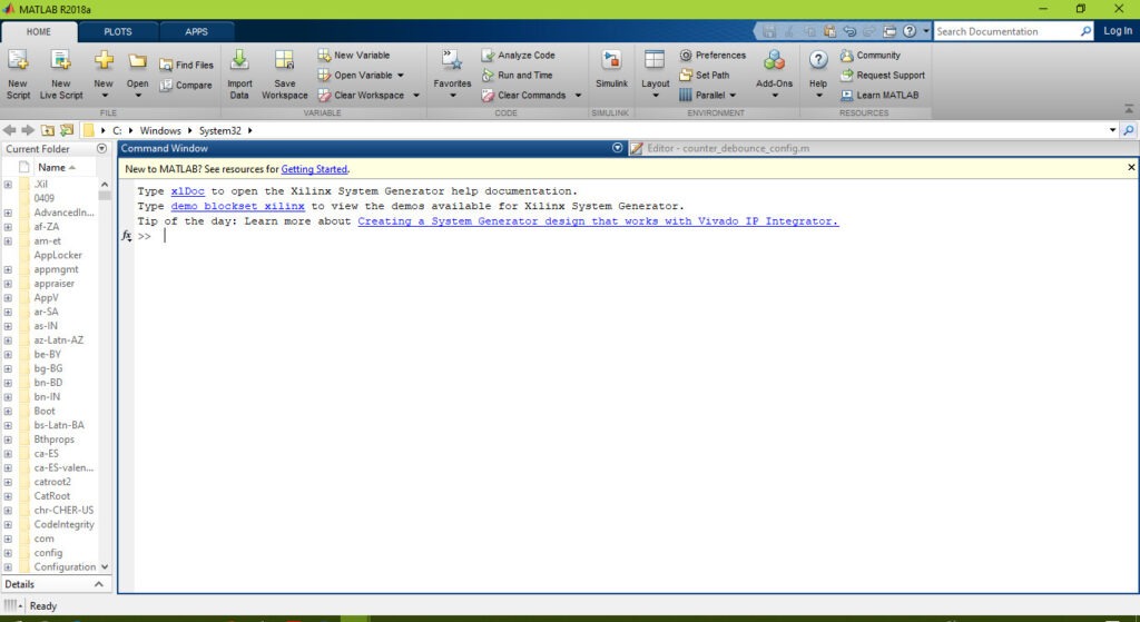
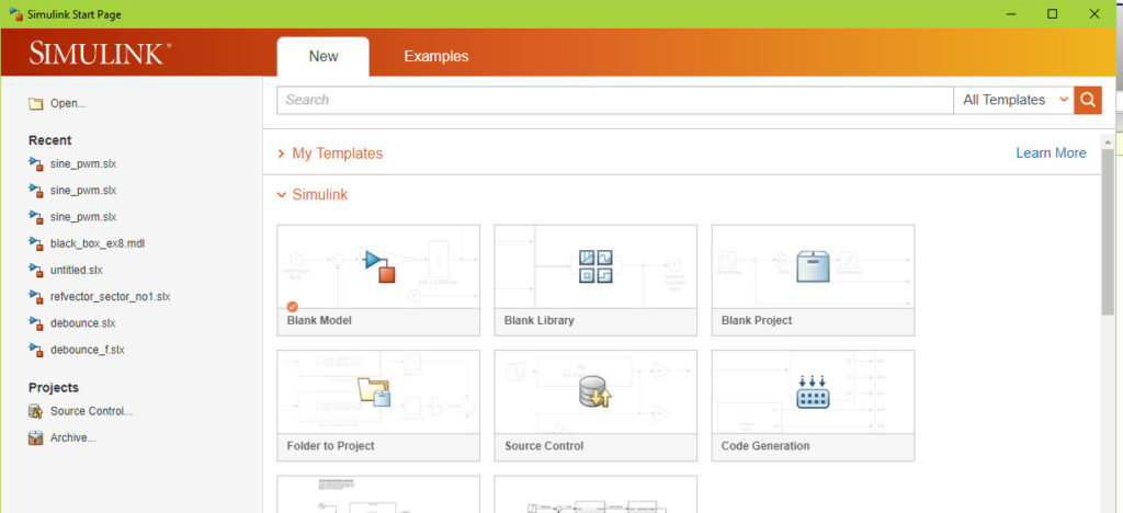
This will open the “MATLAB R2018a” window which is shown in below and Click on the Simulink option.
Step 2: To create a new Simulink model, choose Blank Model.
This will open the following blank window which allows us to describe the block diagram of counter
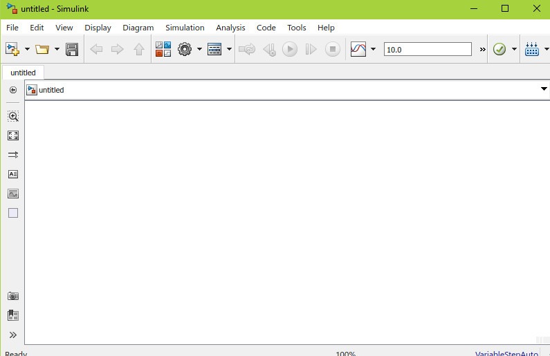
Step 3: Click on the Library icon. This will open the “Simulink Library Browser”
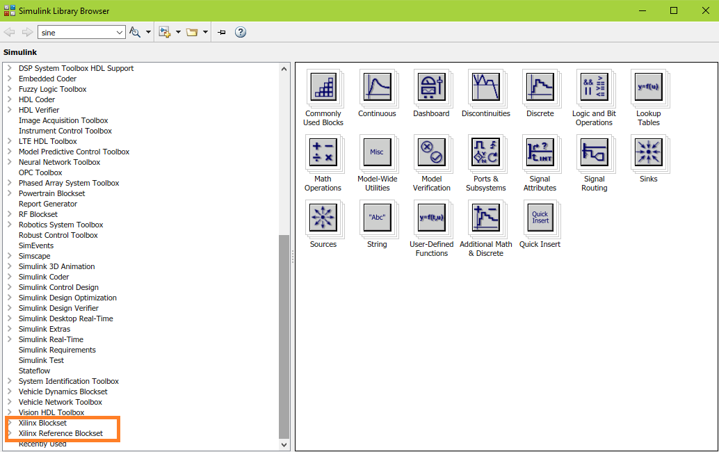
As shown in the figure, the following two Xilinx categories should be added to the list of the libraries:
- Xilinx Blockset
- Xilinx Reference Blockset
In the rest of the guide, we will add the required building blocks and review the important settings in each block’s dialog box. For more information about the configurable parameters of the different blocks, please refer to this Xilinx document.
Step 4: Add the “Counter” block that can be found in the
“Xilinx Blockset\Basic Elements” category.
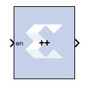
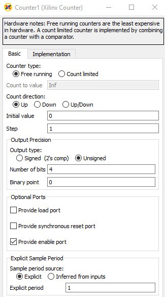
The block has one enable input port and one 4 bit output port. We will give the parameters of the “Basic” tab as given above. To have a 4 bit counter, we set the “Number of bits” to 4 and the “Binary point” to zero. This means that the output is a 4-bit integer. we don’t need to define a fractional output but, if we had set the “Number of bits” to 4 and the “Binary point” to 2, 2 bits out of the total 4 bits of the output will be considered to the right of the binary point.
In “Optional port” check the “provide enable port”.
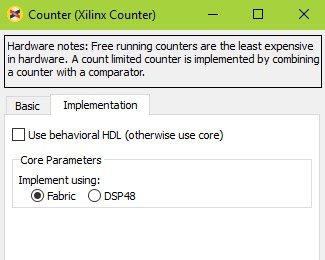
Below figure shows the “Implementation” tab of the block. In this page, you can choose to implement the counter using either the Fabric or the DSP48 slices. For a discussion about the difference between the two choices, refer to the mentioned article. We will leave it as it’s by default, i.e. implement using the Fabric.
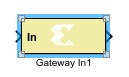
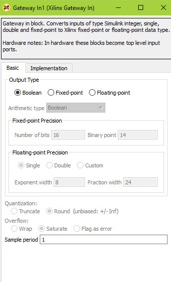
Step 5: Add the “Gateway in” by choosing
“Xilinx Blockset\Basic Elements” category.
Give the output type as Boolean in “Basic” tab and leave “implementation” tab as it’s by default
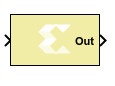
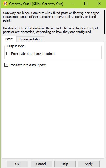
Step 6: Add the “Gateway out” by choosing
“Xilinx Blockset\Basic Elements” category.
Leave the Gateway Out parameters as it’s by default.
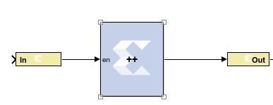
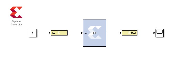
Step 7: Connecting the discussed blocks according to block diagram, we obtain the schematic shown in below.
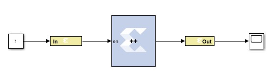
Step 8: The model is almost complete but we need some other blocks to simulate the system. Add constant block and set it as 1. So the input signal will be high. Add the scope block to see the simulation result.
Step 9: Add the System generator by choosing
“Xilinx Blockset\Basic Elements” category.

Step 10: The Simulink window should be like this below.
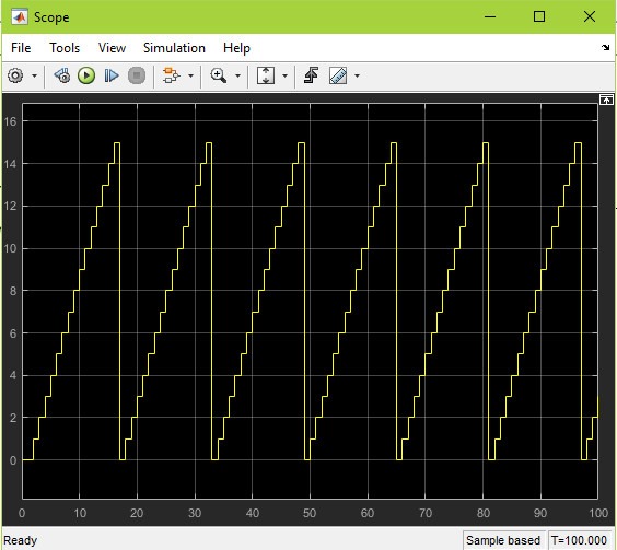
By clicking the “Run” button of Simulink, we get the following curve on the “Scope”.
Step 11: After verifying the simulation output double click on the System generator block
Xilinx System Generator Block
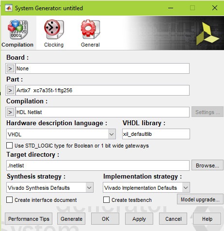
Any Simulink model that uses Xilinx blocks must include a “System Generator” block. This block allows us to control the system and simulation parameters. It also handles HDL code generation.
Step 12: You should also choose the target device from the “Part” parameter of the dialog box and give the software the destination folder to store the generated files in the “Target directory”.
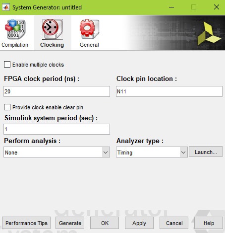
Step 13: In the “Clocking tab” set the FPGA Clock period and Clock pin location. Now we can generate the VHDL description of the model by pushing the “Generate” button in figure.
Step 14: Once the generation is finished, it will appear like this below
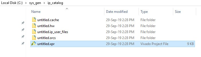
Step 15: Go to the Target directory> ip_catalog and double click on the .xpr shown below.
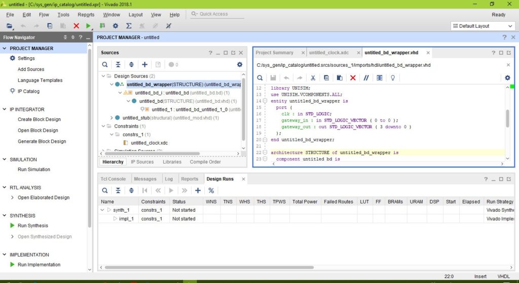
Vivado Design suite window open like this shown below
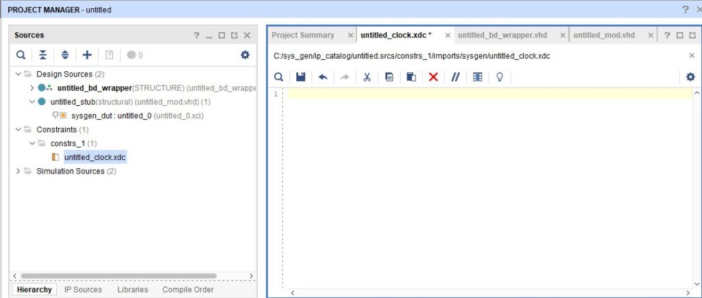
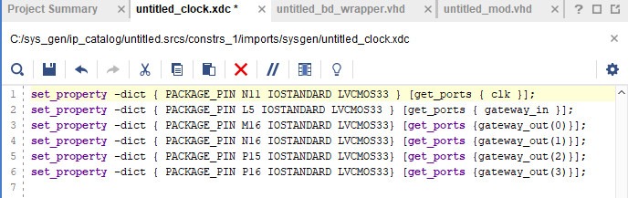
Step 16: Click on the .xdc file in the source window of constraints to open on the right side of console and remove the XDC to make it as a blank console.
Step 17: Copy the following XDC File and paste it on the blank XDC window created.
set_property -dict { PACKAGE_PIN N11 IOSTANDARD LVCMOS33 } [get_ports { clk }];
set_property -dict { PACKAGE_PIN L5 IOSTANDARD LVCMOS33 } [get_ports { gateway_in }];
set_property -dict { PACKAGE_PIN J3 IOSTANDARD LVCMOS33 } [get_ports { gateway_out[0] }];
set_property -dict { PACKAGE_PIN H3 IOSTANDARD LVCMOS33 } [get_ports { gateway_out[1] }];
set_property -dict { PACKAGE_PIN J1 IOSTANDARD LVCMOS33 } [get_ports { gateway_out[2] }];
set_property -dict { PACKAGE_PIN K1 IOSTANDARD LVCMOS33} [get_ports { gateway_out[3] }];
It should be shown below.
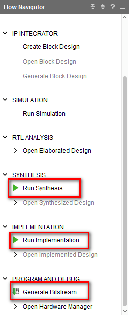
Step 18: Perform synthesis, Implementation and generate bitstream by click them one by one in Flow Navigator
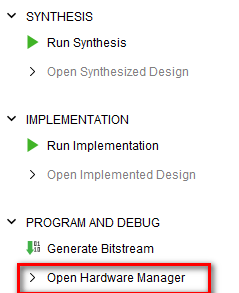
Step 19: Click Open Hardware Manager in Flow Navigator to program the bit file.
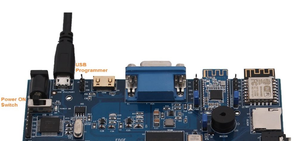
Step 20: Connect EDGE Artix 7 FPGA Kit to PC through USB cable and Turn On the kit.
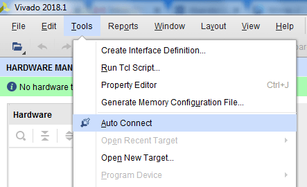
Step 21: To detect FPGA, Do Hardware Manager -> Open Target -> Auto Connect
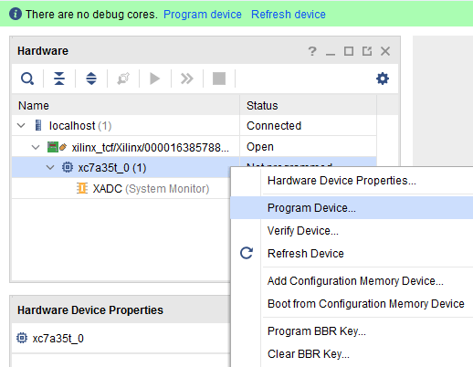
Step 22: If the device is detected successfully, then select Program Device by right click on the target device xc7a35t_0 as shown below
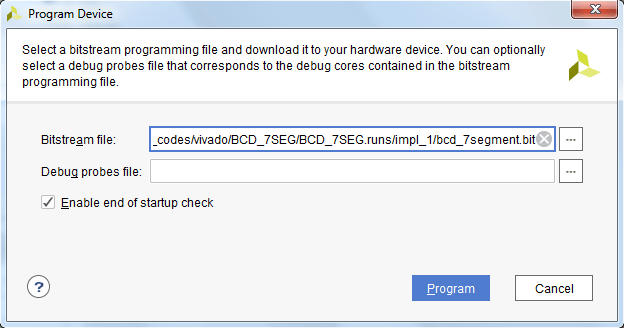
Step 23: Browse the Bit file need to be downloaded to the Artix 7 FPGA and click Program.
C:\sys_gen\ip_catalog\untitled.runs\impl_1/counter.bit
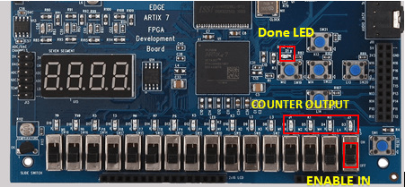
Step 24: Once the Program Succeeds, Done LED D1 light up on EDGE Artix 7 FPGA kit. Enable the counter by the slide switch and verify the counter output through 4 LEDs.
-
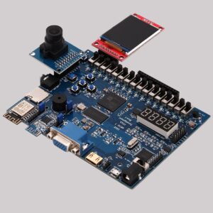 EDGE Artix 7 FPGA Development Board₹ 13,750