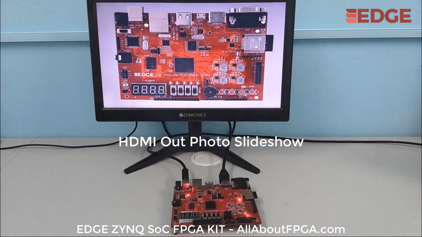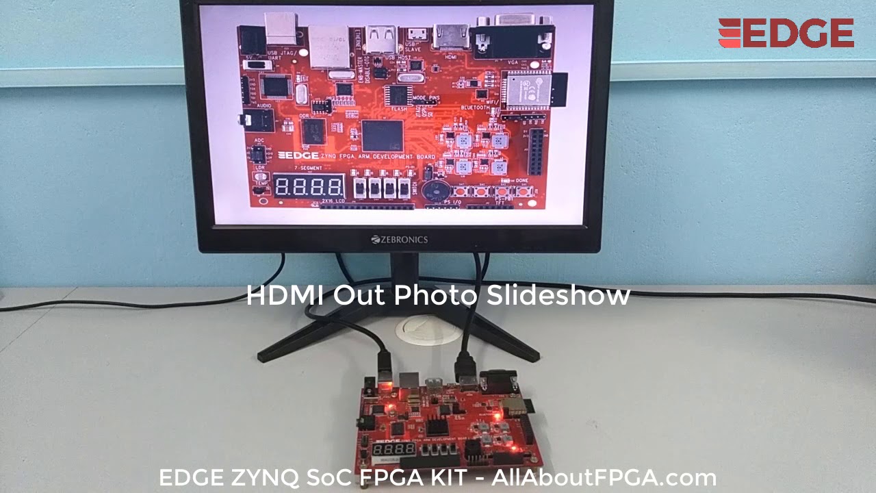
In this demo photos are displayed in HDMI monitor as a slideshow. HDMI interface present on PL side is connected to ZYNQ PS via AXI interface.

The display on the HDMI is achieved by the DMA.
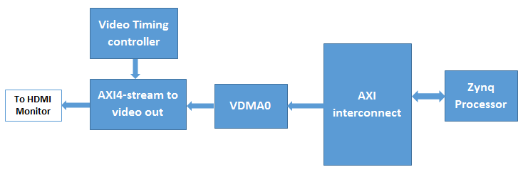
DMA system reads the data from the DDR3 memory and display it on the hdmi monitor.
VDMA sent over the HDMI interface.
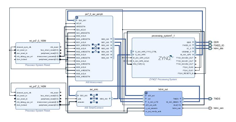
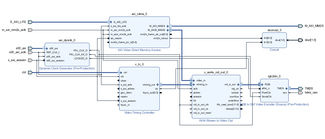
The Expanded view of hdmi_out block
Since the VDMA display is a very important element, this experiment will detail
the build process Vivado
We have used VDMA IP to display image on HDMI. VDMA is a very key IP in Xilinx’s video processing. VDMA is a special DMA, which is specially designed for video processing. As shown in the figure above, we see that VDMA has an AXI4 Memory Map interface for reading and writing video data to the memory, an AXI4-Lite interface for reading VDMA status and configuring VDMA parameters, and an AXI4-Stream interface. Used for video input and output.
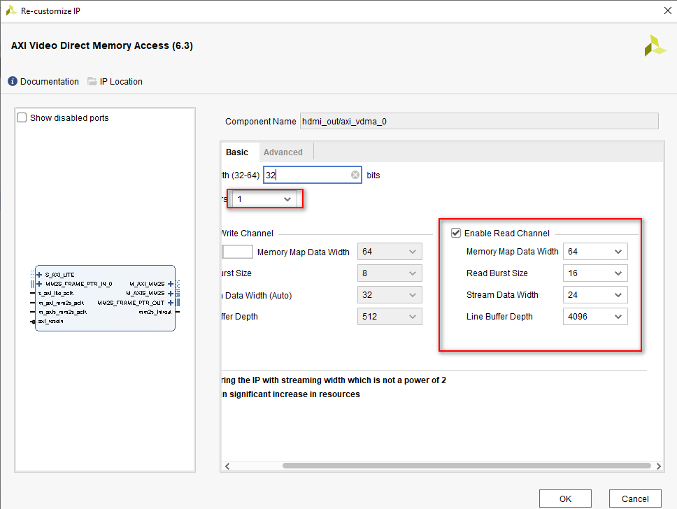
For the configuration of AXI_VDMA0, we only enable the read channel here, and the write channel is disabled. In the Advanced tab, we select master in our Genlockmode Options and enable unaligned transmission.
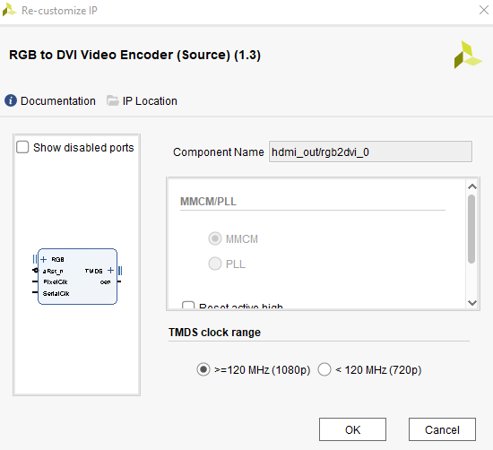
RGB to DVI IP directly to raw transition-minimized differential signaling (TMDS) clock and data channel output as defined in DVI 1.0 specs for source devices. It encodes 24-bit RGB video data along with the pixel clock and synchronization signals.
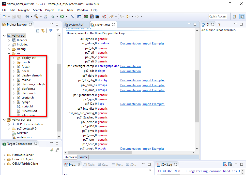
SDK application development
Open the SDK. In VDMA_out application project, added display_ctrl, dynclk, artix.h, box.h, display_demo.h, Spartan.h, zynq.h and main.c.
Artix, Spartan and zynq are the images which are converted into hex values and added as artix.h,Spartan.h, zynq.h and box.h.
In the main function of display_demo.c, resetting the HDMI and sensor, and initialize the sensor.
On-board verification
Connect the board and HDMI monitor as shown
Below.
Click on the program FPGA symbol to download the bit file.
Now, the done LED will be ON
Click on the vdma_out application project ->Run us ->
Launch on hardware ( system debugger) as shown below.
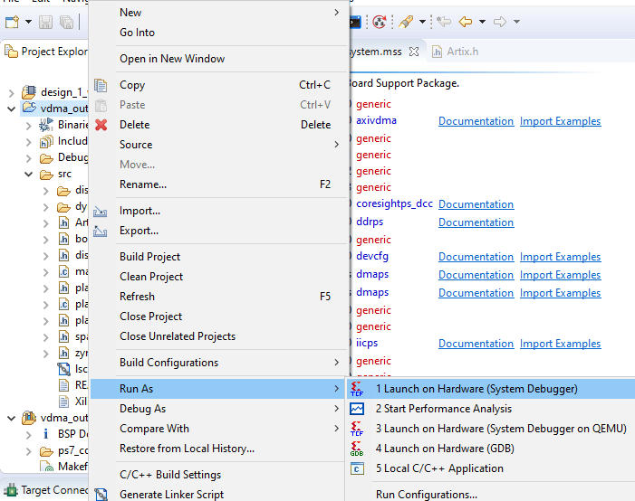
After the program runs, you can see the slideshow image on the HDMI monitor.