Table of Contents
ALU
ALU internally always do multiple operations like addition, subtraction, division and multiplication. We have to specify which result you want to return as an output by using control lines. In this tutorial, We are implementing 3 bit ALU with Adder, Subtractor, Multiplier and comparator.
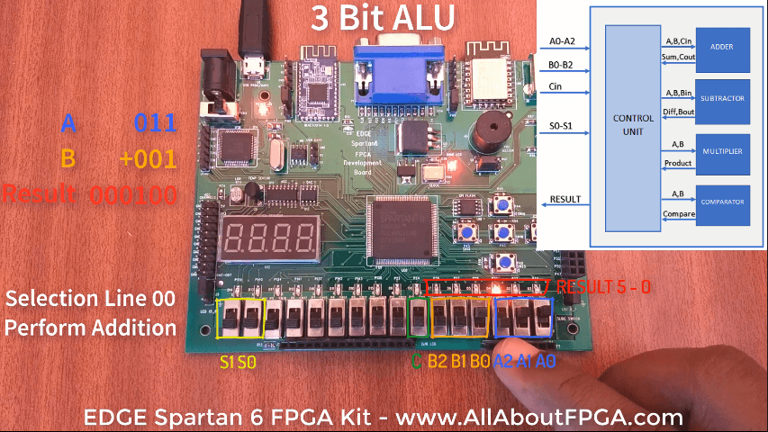
To perform this ALU Demo, we are using Slide Switch as Input and LEDs as Output on EDGE Spartan 6 FPGA Kit.Each of the Modules are constructed structurally for better understanding of combination circuit design and port mapped to the Top level ALU.
For behavioural implementation of ALU refer the VHDL code for 4 bit ALU.
Block diagram of the ALU
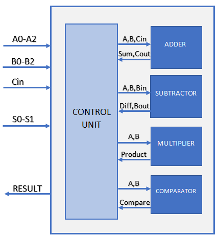
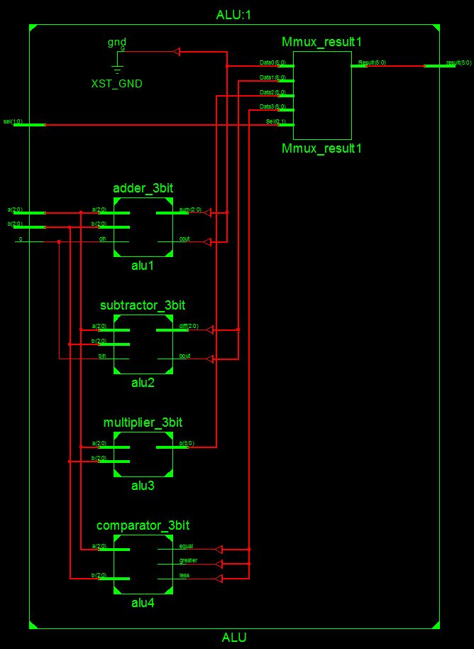
Top Module consist of 3 bit Adder, subractor, multiplier and comparator as a Port mapped components and 2 bit mux to select the output result.
VHDL Code for Top Module ALU
library IEEE; use IEEE.STD_LOGIC_1164.ALL; entity ALU is Port ( a : in STD_LOGIC_VECTOR (2 downto 0); b : in STD_LOGIC_VECTOR (2 downto 0); c: in std_logic; sel : in STD_LOGIC_VECTOR (1 downto 0); result : out STD_LOGIC_VECTOR (5 downto 0)); end ALU; architecture Behavioral of ALU is component comparator_3bit port( a : in std_logic_vector(2 downto 0); b : in std_logic_vector(2 downto 0); less : out std_logic; equal : out std_logic; greater : out std_logic); end component; component multiplier_3bit Port ( a : in STD_LOGIC_VECTOR (2 downto 0); b : in STD_LOGIC_VECTOR (2 downto 0); p : out STD_LOGIC_VECTOR (5 downto 0)); end component; component subtractor_3bit Port ( a : in STD_LOGIC_VECTOR (2 downto 0); b : in STD_LOGIC_VECTOR (2 downto 0); bin : in STD_LOGIC; diff : out STD_LOGIC_VECTOR (2 downto 0); bout : out STD_LOGIC); end component; component adder_3bit is Port ( a : in STD_LOGIC_VECTOR (2 downto 0); b : in STD_LOGIC_VECTOR (2 downto 0); cin : in STD_LOGIC; sum : out STD_LOGIC_VECTOR (2 downto 0); cout : out STD_LOGIC); end component; signal t_comp,t_multi,t_sub,t_adder:std_logic_vector(5 downto 0):= (others =&amp;gt; '0'); begin alu1: adder_3bit port map(a=>a,b=>b,cin=>c,sum=>t_adder(2 downto 0),cout=>t_adder(3)); alu2: subtractor_3bit port map(a=>a,b=>b,bin=>c,diff=>t_sub(2 downto 0),bout=>t_sub(3)); alu3: multiplier_3bit port map(a=>a,b=>b,p=>t_multi); alu4: comparator_3bit port map(a=>a,b=>b,less=>t_comp(0),equal=>t_comp(1),greater=>t_comp(2)); process(sel,t_comp,t_multi,t_sub,t_adder) begin case sel is when "00"=> result<=t_adder; when "01"=> result<=t_sub; when "10"=> result<=t_multi; when "11"=> result<=t_comp; when others => result<="000000"; end case; end process; end Behavioral;
Schematic diagram shows the complete ALU architecture implemented
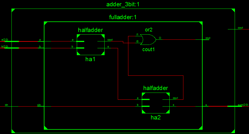
3 bit Adder unit is constructed using Full Adder. Full Adder is constructed using Half Adder
VHDL Code for 3 bit Adder
library IEEE;
use IEEE.STD_LOGIC_1164.ALL;
entity adder_3bit is
Port ( 	a : in STD_LOGIC_VECTOR (2 downto 0);
		b : in STD_LOGIC_VECTOR (2 downto 0);
		cin : in STD_LOGIC;
		sum : out STD_LOGIC_VECTOR (2 downto 0);
		cout : out STD_LOGIC);
end adder_3bit;

architecture Behavioral of adder_3bit is

component fulladder
port( 	a : in STD_LOGIC;
		b : in STD_LOGIC;
		cin : in STD_LOGIC;
		s : out STD_LOGIC;
		cout : out STD_LOGIC);
end component;

signal c1,c2:std_logic;
begin
fa1:fulladder port map(a(0),b(0),cin,sum(0),c1);
fa2:fulladder port map(a(1),b(1),c1,sum(1),c2);
fa3:fulladder port map(a(2),b(2),c2,sum(2),cout);
end Behavioral;
VHDL Code for Full Adder
library IEEE;
use IEEE.STD_LOGIC_1164.ALL;

entity fulladder is
port( 	a : in STD_LOGIC;
		b : in STD_LOGIC;
		cin : in STD_LOGIC;
		s : out STD_LOGIC;
		cout : out STD_LOGIC);
end fulladder;

architecture Behavioral of fulladder is
component halfadder
Port( 	a,b : in std_logic;
		s : out STD_LOGIC;
		cout : out STD_LOGIC);
end component;
signal s1,c1,c2:std_logic;

begin
ha1: halfadder port map(a,b,s1,c1);
ha2: halfadder port map(s1,cin,s,c2);
cout <= c1 or c2;
end Behavioral;
VHDL Code for Half Adder
library IEEE;
use IEEE.STD_LOGIC_1164.ALL;

entity halfadder is
Port( 	a,b : in std_logic;
		s : out STD_LOGIC;
		cout : out STD_LOGIC);
end halfadder;

architecture Behavioral of halfadder is
begin
s <= a xor b;
cout <= a and b;
end Behavioral;
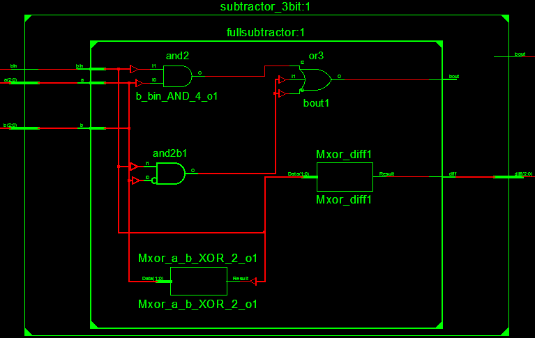
3 Bit subtractor is constructed using 3 full subtractors as shown in schematics
VHDL Code for 3 bit Subtractor
library IEEE;
use IEEE.STD_LOGIC_1164.ALL;
entity subtractor_3bit is
Port ( 	a : in STD_LOGIC_VECTOR (2 downto 0);
		b : in STD_LOGIC_VECTOR (2 downto 0);
		bin : in STD_LOGIC;
		diff : out STD_LOGIC_VECTOR (2 downto 0);
		bout : out STD_LOGIC);
end subtractor_3bit;
architecture Behavioral of subtractor_3bit is
component fullsubtractor is
Port(	a : in STD_LOGIC;
		b : in STD_LOGIC;
		bin : in STD_LOGIC;
		diff : out STD_LOGIC;
		bout : out STD_LOGIC);
end component;
signal br0,br1: std_logic;
begin
fs1: fullsubtractor port map(a(0),b(0),bin,diff(0),br0);
fs2: fullsubtractor port map(a(1),b(1),br0,diff(1),br1);
fs3: fullsubtractor port map(a(2),b(2),br1,diff(2),bout);
end Behavioral;
VHDL Code for Full Subtractor
library IEEE;
use IEEE.STD_LOGIC_1164.ALL;
entity fullsubtractor is
Port ( 	a : in STD_LOGIC;
		b : in STD_LOGIC;
		bin : in STD_LOGIC;
		diff : out STD_LOGIC;
		bout : out STD_LOGIC);
end fullsubtractor;
architecture Behavioral of fullsubtractor is
begin
diff <= a xor b xor bin;
bout <= ((not a)and b)or((not a)and bin)or(b and bin);
end Behavioral;
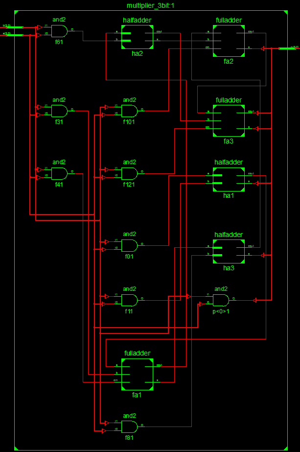
3 Bit multiplier is implemented using Full Adder, Half Adder and AND gates as shown in Schematics
VHDL Code for 3 bit Multiplier
library IEEE;
use IEEE.STD_LOGIC_1164.ALL;
entity multiplier_3bit is
Port( 	a : in STD_LOGIC_VECTOR (2 downto 0);
		b : in STD_LOGIC_VECTOR (2 downto 0);
		p : out STD_LOGIC_VECTOR (5 downto 0));
end multiplier_3bit;

architecture Behavioral of multiplier_3bit is
component fulladder;
Port( 	a : in STD_LOGIC;
		b : in STD_LOGIC;
		cin : in STD_LOGIC;
		s : out STD_LOGIC;
		cout : out STD_LOGIC);
end component;
component halfadder is
port( 	a,b : in std_logic;
		s : out STD_LOGIC;
		cout : out STD_LOGIC);
end component;
signal f0,f1,f2,f3,f4,f5,f6,f7,f8,f9,f10,f11,f12,s1,s2: std_logic;
begin
ha1: halfadder port map(f0,f1,p(1),f2);
fa1: fulladder port map(f2,f3,f4,s1,f5);
ha2: halfadder port map (f5,f6,s2,f7);
ha3: halfadder port map (s1,f8,p(2),f9);
fa2: fulladder port map (f9,s2,f10,p(3),f11);
fa3: fulladder port map (f11,f7,f12,p(4),p(5));
f0 <= a(0) and b(1);
f1 <= a(1) and b(0);
f3 <= a(0) and b(2);
f4 <= a(1) and b(1);
f6 <= a(1) and b(2);
f8 <= a(2) and b(0);
f10<= a(2) and b(1);
f12<= a(2) and b(2);
P(0)<=a(0) and b(0);
end Behavioral;
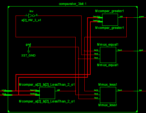
Finally comparator unit is constructed behaviourally as shown in schematics
VHDL Code for 3 bit comparator
library IEEE;
use IEEE.STD_LOGIC_1164.ALL;
entity comparator_3bit is
Port ( 	a : in std_logic_vector(2 downto 0);
		b : in std_logic_vector(2 downto 0);
		less : out std_logic;
		equal : out std_logic;
		greater : out std_logic);
end comparator_3bit;
architecture Behavioral of comparator_3bit is
begin
process(a,b)
begin
if (a > b ) then --condition a is greater than b
less <= '0';
equal <= '0';
greater <= '1';
elsif (a < b) then --condition a is less than b
less <= '1';
equal <= '0';
greater <= '0';
else --condition a is equals b
less <= '0';
equal <= '1';
greater <= '0';
end if;
end process;
end Behavioral;
Pin Assignment
Lets assign the User Constraint file of EDGE Spartan 6 FPGA kit to ALU
Input A0, A1, A2 ar assigned to Slide switches from LSB.
NET "a(0)" LOC="P22";
NET "a(1)" LOC="P21";
NET "a(2)" LOC="P17";
Input B0,B1,B2 are assigned slide switches next to A input
NET "b(0)" LOC="P16";
NET "b(1)" LOC="P15";
NET "b(2)" LOC="P14";
Carry input is assigned next switch of B input
NET "c" LOC="P12";
Selection lines S0 and S1 are assigned to Slide switches at the MSB Position
NET "sel(0)" LOC="P2";
NET "sel(1)" LOC="P1";
Results 6bit output are assigned to LEDs from LSB position.
NET "result(0)" LOC="P33";
NET "result(1)" LOC="P32";
NET "result(2)" LOC="P30";
NET "result(3)" LOC="P29";
NET "result(4)" LOC="P27";
NET "result(5)" LOC="P26";
FPGA Demonstration of 3 bit ALU
-
 EDGE ZYNQ SoC FPGA Development Board₹ 17,500
 -
 EDGE Artix 7 FPGA Development Board₹ 13,750
 -
 EDGE Spartan 6 FPGA Development Board₹ 8,500

