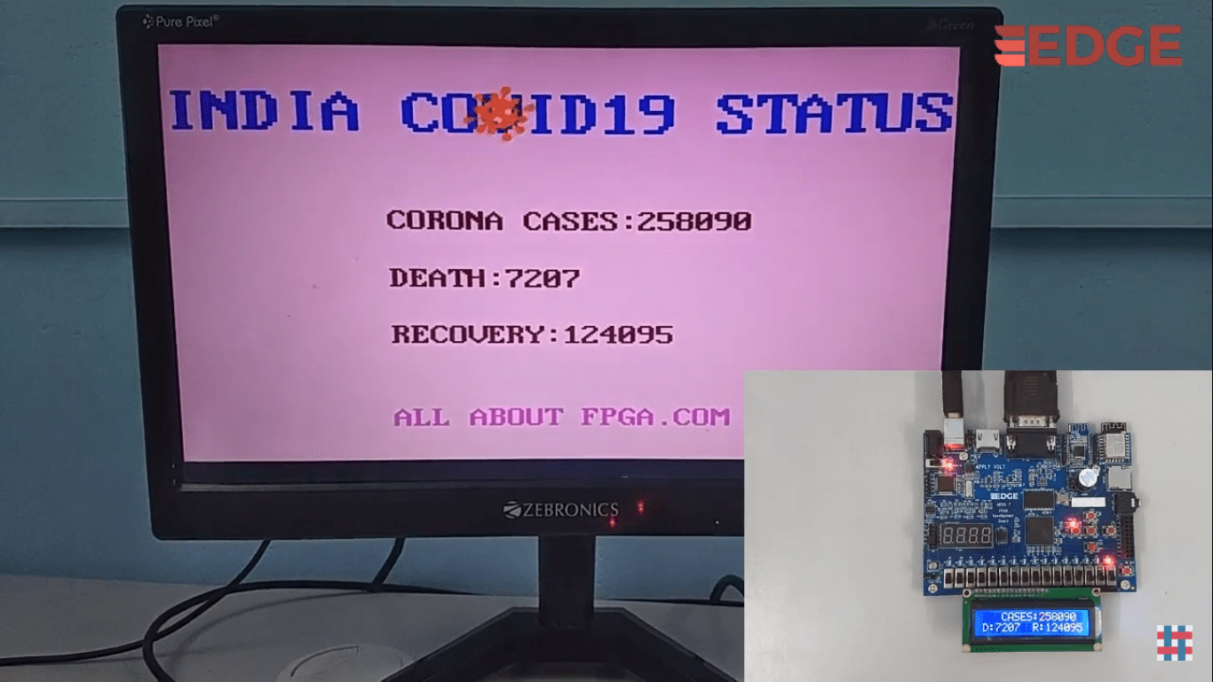
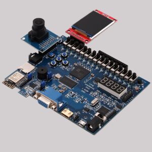
This project visualizes the current data of the coronavirus outbreak of India in real-time on a VGA monitor and also display in 2X16 LCD using EDGE Artix 7 FPGA board.
Table of Contents
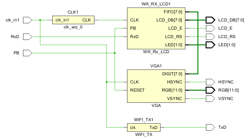
Block Diagram
Flow of operation
In this project, we are reading the Total cases, Death and recovered corona virus cases.
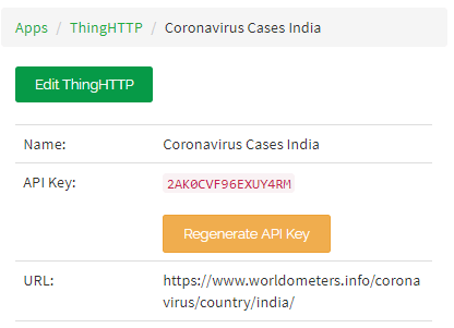
Thingspeak App creation
ThingHTTP App is used to retrieve the covid data from WorldOMeters website.
First create an account in ThingSpeak if you haven’t.
And to show you an example we took the Covid cases in India . Give the name and copy the below given URL (i.e) https://www.worldometers.info/coronavirus/.
Now you go to WorldOmeters, the CoronaVirus meter https://www.worldometers.info/coronavirus/
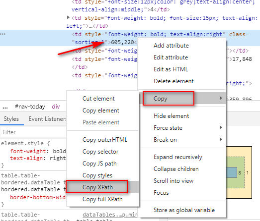
Right Click on the India cases and click on the inspect as shown below
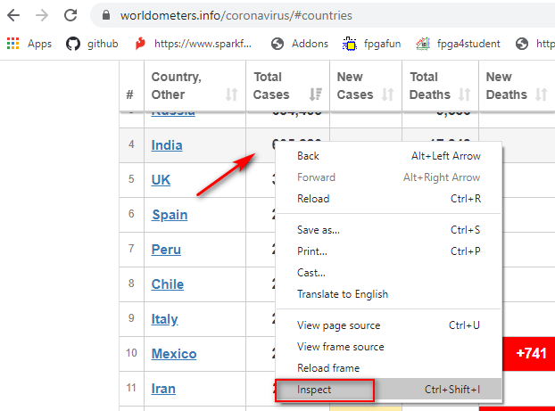
It will bring the new page. Now right click on the highlighted line and copy the xpath as shown below
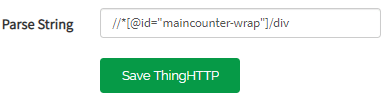
And now you go back to your ThingHTTP we called it “covid19 live outbreak” and scroll down and paste it in Parse String, and press “Save ThingHTTP”
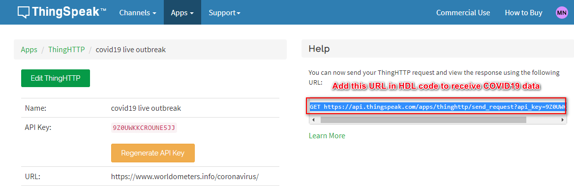
Now you will see the URL in your right hand as shown below.
AT commands for communicaton
We have to program FPGA for ESP8266 to send the required AT commands and to establish a connection between the FPGA and thingspeak server.
Thingspeak.com provides the 16 digit unique API key which helps to get the data from our thingspeak cloud.
we have used multiple AT commands to establish connection between system and thingspeak server. Those are given below
AT+CWJAP=”WIFINAME”,”Password” Enter your wifiname and wifipassword to connect the ESP wifi module which is present in FPGA board to internet.
AT+CIPSTART=”TCP”,”184.106.153.149″,80 Connecting to TCT IP Address of Thingspeak.com cloud
AT+CIPSEND=60 Prepare to send 60 letter of words to thingspeak
GET /apps/thinghttp/send_request?api_key=2AK0CVF96EXUY4RM We Request our cloud to receive the data in FPGA.
The RxD is the WIFI receiver port which gets the data from the thingspeak cloud and processes it in the EDGE Artix 7 FPGA board. Then the received data is displayed in the both 2X16 LCD display and VGA monitor as shown below
List of I/O ports and its description
| Clk_in | 50Mhz clock input |
| Pb | logic signal which, when active, resets the system |
| RxD | WIFI reception data line |
| TxD | WIFI transmission data line |
| LCD_RS | Shift between command/data register |
| LCD_E | Toggled between 1 and 0 for data acknowledgement |
| LCD_DB(7:0) | 8 bit data line to send 8 bit data |
| VSYNC | VGA vertical synchronizing line |
| HSYNC | VGA Horizontal synchronizing line |
| RGB(11:0) | 12 bit color data line |
| LED(1:0) | LED outputs for WIFI_RX_LCD state changing |
Project Demo on EDGE Artix 7 FPGA kit

-
 EDGE Artix 7 FPGA Development Board₹ 13,750