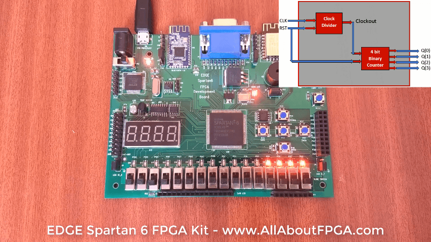
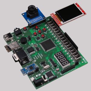
In this tutorial, We implemented 4 bit binary counter using EDGE Spartan 6 FPGA Kit. It counts at every 0.5 sec.
We already designed 4 bit Binary counter for simulation which counts at input clock frequency (20 ns). As a result we can’t visually differentiate the counting sequence with on-board LEDs as it is counting at 20 ns. To implement it on FPGA first design the clock divider to generate 0.5 sec clock from 20 ns.
Clock Divider takes an input frequency of 50MHz and generates an output of frequency of 2Hz.
Next step, provide the clock divider output as a clock input to binary counter.
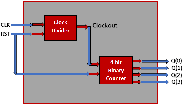
In this section, Top Level Binary counter VHDL code consist of Clock and Reset as input and 4 bit counter output.
We port mapped clock divider and binary counter to the top madule in the following code.
library IEEE;

use IEEE.STD_LOGIC_1164.ALL;

entity binary_counter_1sec is

Port ( clk : in  STD_LOGIC;

rst: in  STD_LOGIC;

q : out  STD_LOGIC_VECTOR (3 downto 0));

end binary_counter_1sec;

architecture Behavioral of binary_counter_1sec is

component Clock_Divider

port ( clk,reset: in std_logic;

clockout: out std_logic);

end Component;

component binary_counter

port(Clock, reset : in std_logic;

Q : out std_logic_vector(3 downto 0));

end component;

signal clk_int: std_logic;

begin

clkdiv : clock_divider port map(clk,rst,clk_int);

counter : binary_counter port map(clk_int,rst,q);

end Behavioral;
VHDL Code for Clock Divider from 50 MHz to 1 Hz. For more details refer the detailed article on Clock Divider.
library IEEE; use IEEE.STD_LOGIC_1164.ALL; use IEEE.numeric_std.ALL; entity clock_divider is port ( clk,reset: in std_logic; clockout: out std_logic); end clock_divider; architecture bhv of clock_divider is signal count: integer:=1; signal tmp : std_logic := '0'; begin process(clk,reset) begin if(reset='1') then count<=1; tmp<='0'; elsif rising_edge(clk) then count <=count+1; if (count = 25000000) then tmp <= NOT tmp; count <= 1; end if; end if; clockout &lt;= tmp; end process; end bhv;
VHDL Code for binary counter at input clock frequency.
library ieee;

use ieee.std_logic_1164.all;

use ieee.std_logic_unsigned.all;

entity binary_counter is

port(Clock,reset : in std_logic;

Q : out std_logic_vector(3 downto 0));

end binary_counter;

architecture bhv of binary_counter is

signal tmp: std_logic_vector(3 downto 0);

begin

process (Clock,reset)

begin

if (reset='1') then

tmp <= "0000";

elsif rising_edge(Clock) then

tmp <= tmp + 1;

end if;

end process;

Q <= tmp;

end bhv;
Our FPGA Kit got 50 MHz External Clock connected to Spartan 6 FPGA.
NET "clk" LOC = p84;
To reset the circuit, SPDT Slide Switch SW2 is assigned.
NET "rst" LOC = p22;
4 bit counter output is assigned to LEDs D2, D3, D4 and D6.
NET "Q[0]" LOC = p33;
NET "Q[1]" LOC = p32;
NET "Q[2]" LOC = p30;
NET "Q[3]" LOC = p29;

-
 EDGE ZYNQ SoC FPGA Development Board₹ 17,500
 -
 EDGE Artix 7 FPGA Development Board₹ 13,750
 -
 EDGE Spartan 6 FPGA Development Board₹ 8,500
For the clock_Divider module I think it should end like
end process;
clockout <= tmp;
end bhv;
Instead of
clockout <= tmp;
end process;
end bhv;