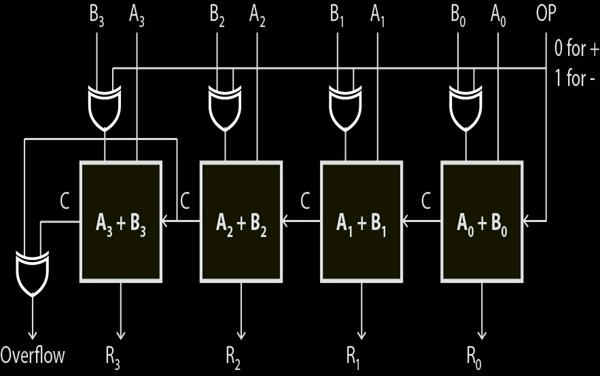
This example describes a two input 4-bit adder/subtractor design in VHDL. The design unit multiplexes add and subtract operations with an OP input. 0 input produce adder output and 1 input produce subtractor output.

VHDL Code for 4-bit Adder / Subtractor
--FULL ADDER
library ieee;
use ieee.std_logic_1164.all;
entity Full_Adder is
   port( X, Y, Cin : in std_logic;
         sum, Cout : out std_logic);
end Full_Adder;

architecture bhv of Full_Adder is
begin
   sum <= (X xor Y) xor Cin;
   Cout <= (X and (Y or Cin)) or (Cin and Y);
end bhv;
========================================================
--4 bit Adder Subtractor
library ieee;
use ieee.std_logic_1164.all;
entity addsub is
   port( OP: in std_logic;
          A,B  : in std_logic_vector(3 downto 0);
          R  : out std_logic_vector(3 downto 0);
          Cout, OVERFLOW : out std_logic);
end addsub;

architecture struct of addsub is
component Full_Adder is
  port( X, Y, Cin : in std_logic;
        sum, Cout : out std_logic);
end component;
signal C1, C2, C3, C4: std_logic;
signal TMP: std_logic_vector(3 downto 0);

begin
TMP <= A xor B;
FA0:Full_Adder port map(A(0),TMP(0),OP, R(0),C1);-- R0
FA1:Full_Adder port map(A(1),TMP(1),C1, R(1),C2);-- R1
FA2:Full_Adder port map(A(2),TMP(2),C2, R(2),C3);-- R2
FA3:Full_Adder port map(A(3),TMP(3),C3, R(3),C4);-- R3
OVERFLOW <= C3 XOR C4 ;
Cout <= C4;
end struct;
Hi thanks for the example.
Quick question: why is line 39 included as I was under the impression that C4/Cout was already classed as the overflow, so why include it at all and include C3 as an overflow ??
Thanks
TMP<= A xor B;
statement is replaced by
TMP(0)<= OP xor B(0);TMP(1)<= OP xor B(1);TMP(2)<= OP xor B(2);TMP(3)<= OP xor B(3);
THEN it gives correct output.
you can also just put OP instead of A