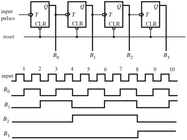
The clock inputs of all the flip-flops are connected together and are triggered by the input pulses. Thus, all the flip-flops change state simultaneously (in parallel).
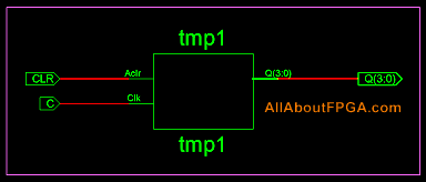
VHDL Code for 4-bit binary counter
library ieee;
use ieee.std_logic_1164.all;
use ieee.std_logic_unsigned.all;
entity vhdl_binary_counter is
port(C, CLR : in std_logic;
Q : out std_logic_vector(3 downto 0));
end vhdl_binary_counter;
architecture bhv of vhdl_binary_counter is
signal tmp: std_logic_vector(3 downto 0);
begin
process (C, CLR)
begin
if (CLR=’1′) then
tmp <= "0000";
elsif (C’event and C=’1′) then
tmp <= tmp + 1;
end if;
end process;
Q <= tmp;
end bhv;
you are showing timing diagram of down counter, it does not match the code.
Here You are showing timing diagram of down counter .. that creating confusion .. please correct it .