Table of Contents
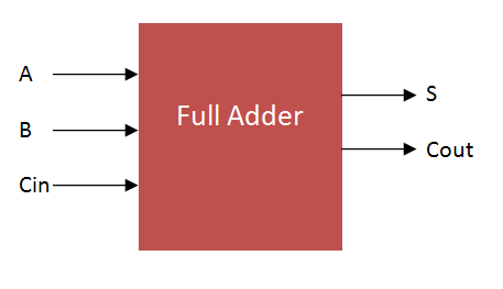
Full Adder
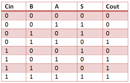
The VHDL Code for full-adder circuit adds three one-bit binary numbers (A B Cin) and outputs two one-bit binary numbers, a sum (S) and a carry (Cout). Truth Table describes the functionality of full adder. sum(S) output is High when odd number of inputs are High. Cout is High, when two or more inputs are High. VHDL Code for full adder can also be constructed with 2 half adder Port mapping in to full adder.
Full Adder Truth Table
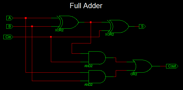
Full Adder Logic Circuit

VHDL Code for Full Adder
 library IEEE;
use IEEE.STD_LOGIC_1164.ALL;

entity full_adder_vhdl_code is
 Port ( A : in STD_LOGIC;
 B : in STD_LOGIC;
 Cin : in STD_LOGIC;
 S : out STD_LOGIC;
 Cout : out STD_LOGIC);
end full_adder_vhdl_code;

architecture gate_level of full_adder_vhdl_code is

begin

 S <= A XOR B XOR Cin ;
 Cout <= (A AND B) OR (Cin AND A) OR (Cin AND B) ;

end gate_level;
Testbench VHDL Code for Full Adder
LIBRARY ieee;
USE ieee.std_logic_1164.ALL;

ENTITY Testbench_full_adder IS
END Testbench_full_adder;

ARCHITECTURE behavior OF Testbench_full_adder IS

 -- Component Declaration for the Unit Under Test (UUT)

 COMPONENT full_adder_vhdl_code
 PORT(
 A : IN std_logic;
 B : IN std_logic;
 Cin : IN std_logic;
 S : OUT std_logic;
 Cout : OUT std_logic
 );
 END COMPONENT;

 --Inputs
 signal A : std_logic := '0';
 signal B : std_logic := '0';
 signal Cin : std_logic := '0';

 --Outputs
 signal S : std_logic;
 signal Cout : std_logic;

BEGIN

 -- Instantiate the Unit Under Test (UUT)
 uut: full_adder_vhdl_code PORT MAP (
 A => A,
 B => B,
 Cin => Cin,
 S => S,
 Cout => Cout
 );

 -- Stimulus process
 stim_proc: process
 begin
 -- hold reset state for 100 ns.
 wait for 100 ns;

 -- insert stimulus here
 A <= '1';
 B <= '0';
 Cin <= '0';
 wait for 10 ns;

 A <= '0';
 B <= '1';
 Cin <= '0';
 wait for 10 ns;

 A <= '1';
 B <= '1';
 Cin <= '0';
 wait for 10 ns;

 A <= '0';
 B <= '0';
 Cin <= '1';
 wait for 10 ns;

 A <= '1';
 B <= '0';
 Cin <= '1';
 wait for 10 ns;

 A <= '0';
 B <= '1';
 Cin <= '1';
 wait for 10 ns;

 A <= '1';
 B <= '1';
 Cin <= '1';
 wait for 10 ns;

 end process;

END;
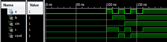
Output Waveform for full adder VHDL Code
I have typed all the same as the code above both for model and testbench. But in simulation I don’t see the square wave. I just see flat lines. Could you comment what I must change?
What do i do about that? I have the same code, small differences, but i get this message. My syntax is correct.
Error (10533): VHDL Wait Statement error at FULL_ADDER_TB.vhd(32): Wait Statement must contain condition clause with UNTIL keyword
Can someone tell me how to run it in model sim???
I have a problem when compile the program.
The error is EOF syntax error.
I want the reason , y it’s happend.
I USED VHDL BUT I CANT GET ADDING OF ANY 7 NO.S PLZ HELP ME
4 bit ALU
i want 16-bit kaggestone full adder vlsi code pls send me the code to my mali…..email:hemanthnani1438@gmail.com
This s not behavioral modeling ,This is dataflow modeling.
Yes correct. The xilinx tool automatically generate architecture name by default as behavioral.
Your truth table is wrong! Please correct for others.
Thanks john, truth table is corrected now.
The truth table is still incorrect. Here is the correct truth table:
http://hyperphysics.phy-astr.gsu.edu/hbase/Electronic/fulladd.html
Fixed Again Thanks 🙂