Table of Contents
Multiplexer
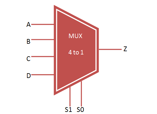
Multiplexer (MUX) select one input from the multiple inputs and forwarded to output line through selection line. It consist of 2 power n input and 1 output. The input data lines are controlled by n selection lines.
For Example, if n = 2 then the mux will be of 4 to 1 mux with 4 input, 2 selection line and 1 output as shown below.

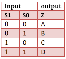
Truth Table for Multiplexer 4 to 1
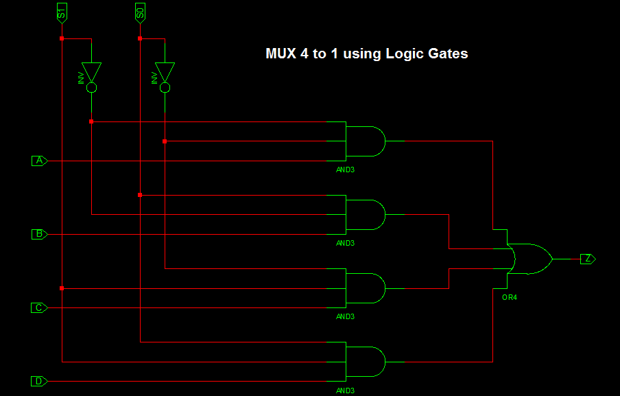
Mux 4 to 1 design using Logic Gates
VHDL Code For 4 to 1 Multiplexer
library IEEE;
use IEEE.STD_LOGIC_1164.all;

entity mux_4to1 is
 port(

     A,B,C,D : in STD_LOGIC;
     S0,S1: in STD_LOGIC;
     Z: out STD_LOGIC
  );
end mux_4to1;

architecture bhv of mux_4to1 is
begin
process (A,B,C,D,S0,S1) is
begin
  if (S0 ='0' and S1 = '0') then
      Z <= A;
  elsif (S0 ='1' and S1 = '0') then
      Z <= B;
  elsif (S0 ='0' and S1 = '1') then
      Z <= C;
  else
      Z <= D;
  end if;

end process;
end bhv;
VHDL TestBench Code for 4 to 1 Multiplexer
LIBRARY ieee;
USE ieee.std_logic_1164.ALL;

ENTITY tb_mux IS
END tb_mux;

ARCHITECTURE behavior OF tb_mux IS

    -- Component Declaration for the Unit Under Test (UUT)

    COMPONENT mux_4to1
    PORT(
         A : IN  std_logic;
         B : IN  std_logic;
         C : IN  std_logic;
         D : IN  std_logic;
         S0 : IN  std_logic;
         S1 : IN  std_logic;
         Z : OUT  std_logic
        );
    END COMPONENT;

   --Inputs
   signal A : std_logic := '0';
   signal B : std_logic := '0';
   signal C : std_logic := '0';
   signal D : std_logic := '0';
   signal S0 : std_logic := '0';
   signal S1 : std_logic := '0';

 	--Outputs
   signal Z : std_logic;

BEGIN

	-- Instantiate the Unit Under Test (UUT)
   uut: mux_4to1 PORT MAP (
          A => A,
          B => B,
          C => C,
          D => D,
          S0 => S0,
          S1 => S1,
          Z => Z
        );

   -- Stimulus process
   stim_proc: process
   begin
      -- hold reset state for 100 ns.
      wait for 100 ns;

	A <= '1';
	B <= '0';
	C <= '1';
	D <= '0';

	S0 <= '0'; S1 <= '0';

      wait for 100 ns;

	S0 <= '1'; S1 <= '0';

      wait for 100 ns;

	S0 <= '0'; S1 <= '1';

		wait for 100 ns;

	S0 <= '0'; S1 <= '1';

		wait for 100 ns;

	end process;

END;
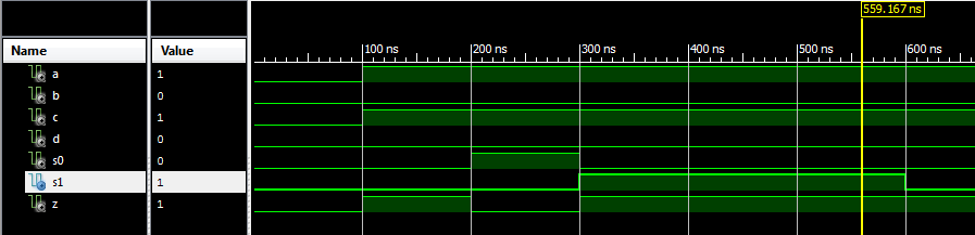
Output Waveform for 4 to 1 Multiplexer
Another Method of Constructing VHDL 4 to 1 mux is by using 2 to 1 Mux. For that implementation first we have write VHDL Code for 2 to 1 Mux and Port map 3 times 2 to 1 mux to construct VHDL 4 to 1 Mux.
4 to 1 Mux Implementation using 2 to 1 Mux
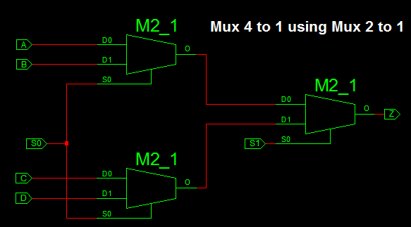
VHDL Code for 2 to 1 Mux
library IEEE;
use IEEE.STD_LOGIC_1164.ALL;

entity mux2_1 is
port(A,B : in STD_LOGIC;
S: in STD_LOGIC;
Z: out STD_LOGIC);
end mux2_1;

architecture Behavioral of mux2_1 is

begin

process (A,B,S) is
begin
if (S ='0') then
Z <= A;
else
Z <= B;
end if;
end process;

end Behavioral;
VHDL 4 to 1 Mux using 2 to 1 Mux
library IEEE;
use IEEE.STD_LOGIC_1164.ALL;

entity mux4_1 is
port(

A,B,C,D : in STD_LOGIC;
S0,S1: in STD_LOGIC;
Z: out STD_LOGIC
);
end mux4_1;

architecture Behavioral of mux4_1 is
component mux2_1
port( A,B : in STD_LOGIC;
S: in STD_LOGIC;
Z: out STD_LOGIC);
end component;
signal temp1, temp2: std_logic;

begin
m1: mux2_1 port map(A,B,S0,temp1);
m2: mux2_1 port map(C,D,S0,temp2);
m3: mux2_1 port map(temp1,temp2,S1,Z);

end Behavioral;
VHDL Testbench and Simulation Waveform for 4 to 1 mux using 2 to 1 mux is same as the above implementation.
very good explanation, thank you!