Table of Contents
DeMultiplexer
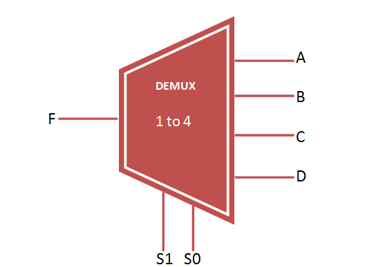
Demultiplexer (DEMUX) select one output from the multiple output line and fetch the single input through selection line. It consist of 1 input and 2 power n output. The output data lines are controlled by n selection lines. For Example, if n = 2 then the demux will be of 1 to 4 mux with 1 input, 2 selection line and 4 output as shown below. Also VHDL Code for 1 to 4 Demux described below.
1 to 4 Demux

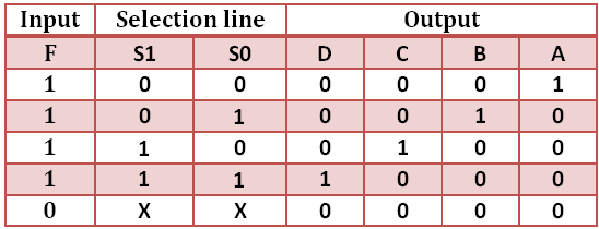
Truth table for Demux 1 to 4
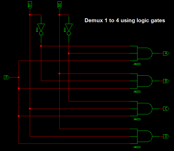
1 to 4 Demux design using Logic Gates
VHDL Code for 1 to 4 Demux
library IEEE;
use IEEE.STD_LOGIC_1164.all;

entity demux_1to4 is
 port(

 F : in STD_LOGIC;
 S0,S1: in STD_LOGIC;
 A,B,C,D: out STD_LOGIC
 );
end demux_1to4;

architecture bhv of demux_1to4 is
begin
process (F,S0,S1) is
begin
 if (S0 ='0' and S1 = '0') then
 A <= F;
 elsif (S0 ='1' and S1 = '0') then
 B <= F;
 elsif (S0 ='0' and S1 = '1') then
 C <= F;
 else
 D <= F;
 end if;

end process;
end bhv;
VHDL Testbench Code for 1 to 4 Demux
LIBRARY ieee;
USE ieee.std_logic_1164.ALL;

ENTITY tb_demux IS
END tb_demux;

ARCHITECTURE behavior OF tb_demux IS

-- Component Declaration for the Unit Under Test (UUT)

COMPONENT demux_1to4
PORT(
F : IN std_logic;
S0 : IN std_logic;
S1 : IN std_logic;
A : OUT std_logic;
B : OUT std_logic;
C : OUT std_logic;
D : OUT std_logic
);
END COMPONENT;

--Inputs
signal F : std_logic := '0';
signal S0 : std_logic := '0';
signal S1 : std_logic := '0';

--Outputs
signal A : std_logic;
signal B : std_logic;
signal C : std_logic;
signal D : std_logic;
-- No clocks detected in port list. Replace <clock> below with
-- appropriate port name

BEGIN

-- Instantiate the Unit Under Test (UUT)
uut: demux_1to4 PORT MAP (
F => F,
S0 => S0,
S1 => S1,
A => A,
B => B,
C => C,
D => D
);

-- Stimulus process
stim_proc: process
begin
-- hold reset state for 100 ns.
wait for 100 ns;

F <= '1';

S0 <= '0'; S1 <= '0';

wait for 100 ns;

S0 <= '1'; S1 <= '0';

wait for 100 ns;

S0 <= '0'; S1 <= '1';

wait for 100 ns;

S0 <= '1'; S1 <= '1';

wait for 100 ns;
-- insert stimulus here

wait;
end process;

END;
Testbench waveform for 1 to 4 Demux

The above waveform represent the result of VHDL Code for 1 to 4 Demux.
The above mentioned code for 1:4 demux (behavioral) is not working properly..pls check this one..
library IEEE;
use IEEE.STD_LOGIC_1164.all;
entity demux_1to4 is
port(
F : in STD_LOGIC;
S0,S1: in STD_LOGIC;
A,B,C,D: out STD_LOGIC
);
end demux_1to4;
architecture bhv of demux_1to4 is
begin
process (F,S0,S1) is
begin
if (S0 =’0′ and S1 = ‘0’) then
A <= F;
B <='0';
C <='0';
D <='0';
elsif (S0 ='1' and S1 = '0') then
A <='0';
B <= F;
C <='0';
D <='0';
elsif (S0 ='0' and S1 = '1') then
A <= '0';
B <= '0';
C <= F;
D <='0';
else
A <= '0';
B <= '0';
C <= '0';
D <= F;
end if;
end process;
end bhv;
S0 and S1 in the truth table are not correct. They are all zero?
Thanks. Demux Selection line S0 and S1 values are updated.
The truth table for the 4-to-1 demux is not correct. Your truth tables describes a binary to one-hot encoder, because the diagonale is filled with ‘1’ instead of F.
Regards
Patrick
Thanks. Now the truth table is fixed.