Table of Contents
Shift Register
VHDL Code for shift register can be categorised in serial in serial out shift register, serial in parallel out shift register, parallel in parallel out shift register and parallel in serial out shift register.
Parallel In – Parallel Out Shift Registers
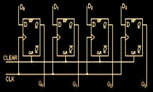
For parallel in – parallel out shift registers, all data bits appear on the parallel outputs immediately following the simultaneous entry of the data bits. The following circuit is a four-bit parallel in – parallel out shift register constructed by D flip-flops.

The D’s are the parallel inputs and the Q’s are the parallel outputs. Once the register is clocked, all the data at the D inputs appear at the corresponding Q outputs simultaneously.
VHDL code for Parallel In Parallel Out Shift Register
library ieee;
use ieee.std_logic_1164.all;

entity pipo is
 port(
 clk : in std_logic;
 D: in std_logic_vector(3 downto 0);
 Q: out std_logic_vector(3 downto 0)
 );
end pipo;

architecture arch of pipo is

begin

 process (clk)
 begin
 if (CLK'event and CLK='1') then
 Q <= D;
 end if;
 end process;

end arch;
Serial In – Parallel Out Shift Registers
For Serial in – parallel out shift registers, all data bits appear on the parallel outputs following the data bits enters sequentially through each flipflop. The following circuit is a four-bit Serial in – parallel out shift register constructed by D flip-flops.

VHDL Code for Serial In Parallel Out Shift Register
library ieee;
use ieee.std_logic_1164.all;

entity sipo is
 port(
 clk, clear : in std_logic;
 Input_Data: in std_logic;
 Q: out std_logic_vector(3 downto 0) );
end sipo;

architecture arch of sipo is

begin

 process (clk)
 begin
 if clear = '1' then
 Q <= "0000";
 elsif (CLK'event and CLK='1') then
 Q(3 downto 1) <= Q(2 downto 0);
 Q(0) <= Input_Data;
 end if;
 end process;
end arch;
there is testbrench for it?
A shift register using jk flipflop code plzzz…
library IEEE;
use IEEE.STD_LOGIC_1164.ALL;
— Uncomment the following library declaration if using
— arithmetic functions with Signed or Unsigned values
–use IEEE.NUMERIC_STD.ALL;
— Uncomment the following library declaration if instantiating
— any Xilinx primitives in this code.
–library UNISIM;
–use UNISIM.VComponents.all;
entity Shift_REG is
Port ( clk : in STD_LOGIC;
sp : in STD_LOGIC;
enb : in STD_LOGIC;
resetn : in STD_LOGIC;
Dsin : in STD_LOGIC;
Dpin : in STD_LOGIC;
Qout : out STD_LOGIC);
end Shift_REG;
architecture Behavioral of Shift_REG
is component nbit_mux_model is
Port ( a,b,sel : in STD_LOGIC;
mout:out std_logic);
end component nbit_mux_model;
component lsfit2_model is
Port ( clk,nrst,enb,D : in STD_LOGIC;
Q,nQ: out std_logic);
end component lsfit2_model;
signal sQout,snQout,sain,sbin,smout: std_logic_vector(3 downto 0);
begin
Rshift_reg_gen: for i in 3 downto 0 generate
Rshift_reg:lsfit2_model
Port map ( clk =>clk,
D=>smout(i),
nrst=>resetn,
enb=>enb,
Q=>sQout(i),
nQ=> snQout(i));
mux1:nbit_mux_model
Port map ( a=>sain(i),
b=>sbin(i) ,mout=>smout(i),sel=>sp);
— Daisy-chain D-FF connection
–Add you code here
a1: if i=3 generate
sain(i)<="1";
end generate a1;
a2: if i<3 generate
sain(i)<="0";
end generate a2;
end generate Rshift_reg_gen;
qout<=sQout;
sbin<=Dpin;
end Behavioral;
is it valid for 4 bit bidirectional shift reg.?
Q: output; you can’t use it as an input too.
an intermediate signal should be used.
————- Correction ———————
library ieee;
use ieee.std_logic_1164.all;
entity sipo is
port(
clk, clear : in std_logic;
Input_Data: in std_logic;
Q: out std_logic_vector(3 downto 0) );
end sipo;
architecture arch of sipo is
signal qout : std_logic_vector ( 3 downto 0);
begin
process (clk)
begin
if clear = ‘1’ then
qout <= "0000";
elsif (CLK'event and CLK='1') then
qout (3 downto 1) <= qout(2 downto 0);
qout(0) <= Input_Data;
end if;
end process;
Q<= qout;
end arch;
—————————————
q is a output, u made it as input it leads an error rite?
What does it do exactly?
‘ Q(3 downto 1) <= Q(2 downto 0);'
it shift content of the q by 1 bit.
Very useful for beginners.
I really apreciate you.
Thank you so much. Its very useful for vhdl beginners.
I really apreciate you.
the example given for PIPO shift register is not actually a shift register, its a storing element, you’re just feeding the input to the output, no bits have been shifted, please revise that!
But that’s how PIPO works, isn’t it?
NVM I understood what you meant, so just add a temp register to store the input and then provide it to the output which will create the shifting…