Table of Contents
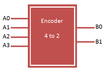
Binary Encoder
Binary encoder has 2n input lines and n-bit output lines. It can be 4-to-2, 8-to-3 and 16-to-4 line configurations. VHDL Code for 4 to 2 encoder can be designed both in structural and behavioral modelling.

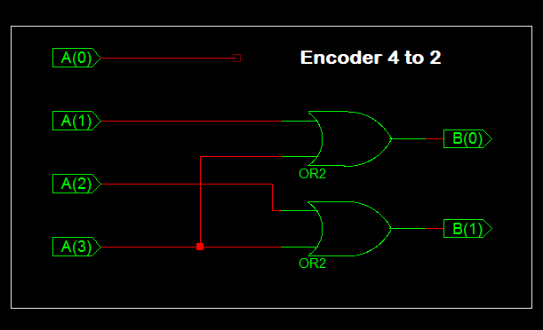
4 to 2 encoder design using logic gates
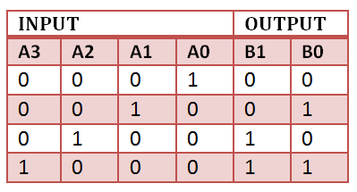
Truth Table for 4 to 2 encoder
VHDL Code for 4 to 2 encoder can be done in different methods like using case statement, using if else statement, using logic gates etc. Here we provide example code for all 3 method for better understanding of the language.
VHDL Code for 4 to 2 encoder using case statement
library IEEE;
use IEEE.STD_LOGIC_1164.all;

entity encoder is
 port(
 a : in STD_LOGIC_VECTOR(3 downto 0);
 b : out STD_LOGIC_VECTOR(1 downto 0)
 );
end encoder;

architecture bhv of encoder is
begin

process(a)
begin
 case a is
 when "1000" => b <= "00"; when "0100" => b <= "01"; when "0010" => b <= "10"; when "0001" => b <= "11"; when others => b <= "ZZ";
 end case;
end process;

end bhv;
VHDL Code for 4 to 2 encoder using if else statement
library IEEE;
use IEEE.STD_LOGIC_1164.all;

entity encoder1 is
 port(
 a : in STD_LOGIC_VECTOR(3 downto 0);
 b : out STD_LOGIC_VECTOR(1 downto 0)
 );
end encoder1;

architecture bhv of encoder1 is
begin

process(a)
begin
 if (a="1000") then
 b <= "00";
 elsif (a="0100") then
 b <= "01";
 elsif (a="0010") then
 b <= "10";
 elsif (a="0001") then
 b <= "11";
 else
 b <= "ZZ";
 end if;
end process;

end bhv;
VHDL Code for 4 to 2 encoder using logic gates
library IEEE;
use IEEE.STD_LOGIC_1164.all;

entity encoder2 is
 port(
 a : in STD_LOGIC_VECTOR(3 downto 0);
 b : out STD_LOGIC_VECTOR(1 downto 0)
 );
end encoder2;

architecture bhv of encoder2 is
begin

b(0) <= a(1) or a(2);
b(1) <= a(1) or a(3);

end bhv;
TestBench VHDL Code for 4 to 2 encoder
LIBRARY ieee;
USE ieee.std_logic_1164.ALL;

ENTITY tb_encoder IS
END tb_encoder;

ARCHITECTURE behavior OF tb_encoder IS

-- Component Declaration for the Unit Under Test (UUT)

COMPONENT encoder
PORT(
a : IN std_logic_vector(3 downto 0);
b : OUT std_logic_vector(1 downto 0)
);
END COMPONENT;

--Inputs
signal a : std_logic_vector(3 downto 0) := (others => '0');

--Outputs
signal b : std_logic_vector(1 downto 0);

BEGIN

-- Instantiate the Unit Under Test (UUT)
uut: encoder PORT MAP (
a => a,
b => b
);

-- Stimulus process
stim_proc: process
begin
-- hold reset state for 100 ns.
wait for 100 ns;

a <= "0000";

wait for 100 ns;

a <= "0001";

wait for 100 ns;

a <= "0010";

wait for 100 ns;

a <= "0100";

wait for 100 ns;

a <= "1000";

wait;
end process;

END;
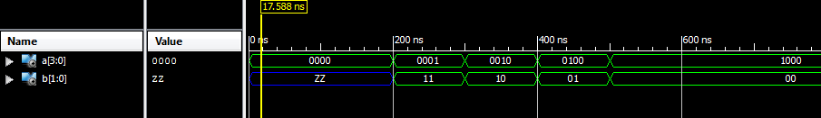
TestBench wave for 4 to 2 encoder
exactly, it’s totally reversed encoding, he should be starting like this
case a is
when “0001” => b b <= "00";
solution 3 :
b(0)<= a(1) or a(3);
b(1)<= a(2) or a(3);
// I think this is how it should be
Maybe you should use a better name than ‘encoder’, because all circuits transforming one code into another code are named encoder and the reverse operation is known as decoder. There is no rule that encoders have a fixed input to output pin ratio of 2 ** n to n (Note: it’s 2 ** n instead of 2 * n in your case).
In your particular case, it’s a “one-hot to binary” encoding. You can also describe one-cold, or Gray-codes this way, but all in all, it’s a simple LUT or ROM, which can be implemented in several ways.
But your example has bigger issues:
1) The truth table describes another function than your VHDL code -> it’s reversed
2) The truth tables has 4 entries, but your first two implementations have 5 entries
3) Why do you assign ‘ZZ’ (tri-state) rather then ‘XX’ or ‘–‘ (don’t care)?
4) Solution 3 has not the same behavior because it can’t return ZZ.
Regards
Patrick