Table of Contents
Ripple Carry Adder
Ripple Carry Adder adds 2 n-bit number plus carry input and gives n-bit sum and a carry output. The Main operation of Ripple Carry Adder is it ripple the each carry output to carry input of next single bit addition. Each single bit addition is performed with full Adder operation (A, B, Cin) input and (Sum, Cout) output. The 4-bit Ripple Carry Adder VHDL Code can be Easily Constructed by Port Mapping 4 Full Adder. The following figure represent the 4-bit ripple carry adder.
4-bit Ripple Carry Adder circuit
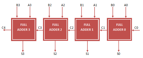
In the above figure, A, B 4-bit input, C0 is Carry in and S 4-bit output , C4 is Carry out. The remaining C1, C2, C3 are intermediate Carry. They are called signals in VHDL Code.
To implement 4 bit Ripple Carry Adder VHDL Code, First implement VHDL Code for full adder .We Already implemented VHDL Code for Full Adder . Now declare full adder entity as component in 4-bit Ripple Carry Adder VHDL Code and do Port Map operation.
4 bit Ripple Carry Adder VHDL Code
library IEEE;
use IEEE.STD_LOGIC_1164.ALL;

entity Ripple_Adder is
Port ( A : in STD_LOGIC_VECTOR (3 downto 0);
B : in STD_LOGIC_VECTOR (3 downto 0);
Cin : in STD_LOGIC;
S : out STD_LOGIC_VECTOR (3 downto 0);
Cout : out STD_LOGIC);
end Ripple_Adder;

architecture Behavioral of Ripple_Adder is

-- Full Adder VHDL Code Component Decalaration
component full_adder_vhdl_code
Port ( A : in STD_LOGIC;
B : in STD_LOGIC;
Cin : in STD_LOGIC;
S : out STD_LOGIC;
Cout : out STD_LOGIC);
end component;

-- Intermediate Carry declaration
signal c1,c2,c3: STD_LOGIC;

begin

-- Port Mapping Full Adder 4 times
FA1: full_adder_vhdl_code port map( A(0), B(0), Cin, S(0), c1);
FA2: full_adder_vhdl_code port map( A(1), B(1), c1, S(1), c2);
FA3: full_adder_vhdl_code port map( A(2), B(2), c2, S(2), c3);
FA4: full_adder_vhdl_code port map( A(3), B(3), c3, S(3), Cout);

end Behavioral;
VHDL Testbench Code for 4-bit Ripple Carry Adder
LIBRARY ieee;
USE ieee.std_logic_1164.ALL;

ENTITY Tb_Ripple_Adder IS
END Tb_Ripple_Adder;

ARCHITECTURE behavior OF Tb_Ripple_Adder IS

-- Component Declaration for the Unit Under Test (UUT)

COMPONENT Ripple_Adder
PORT(
A : IN std_logic_vector(3 downto 0);
B : IN std_logic_vector(3 downto 0);
Cin : IN std_logic;
S : OUT std_logic_vector(3 downto 0);
Cout : OUT std_logic
);
END COMPONENT;

--Inputs
signal A : std_logic_vector(3 downto 0) := (others => '0');
signal B : std_logic_vector(3 downto 0) := (others => '0');
signal Cin : std_logic := '0';

--Outputs
signal S : std_logic_vector(3 downto 0);
signal Cout : std_logic;

BEGIN

-- Instantiate the Unit Under Test (UUT)
uut: Ripple_Adder PORT MAP (
A => A,
B => B,
Cin => Cin,
S => S,
Cout =>; Cout
);

-- Stimulus process
stim_proc: process
begin
-- hold reset state for 100 ns.
wait for 100 ns;
A <= "0110";
B <= "1100";

wait for 100 ns;
A <= "1111";
B <= "1100";

wait for 100 ns;
A <= "0110";
B <= "0111";

wait for 100 ns;
A <= "0110";
B <= "1110";

wait for 100 ns;
A <= "1111";
B <= "1111";

wait;

end process;

END;
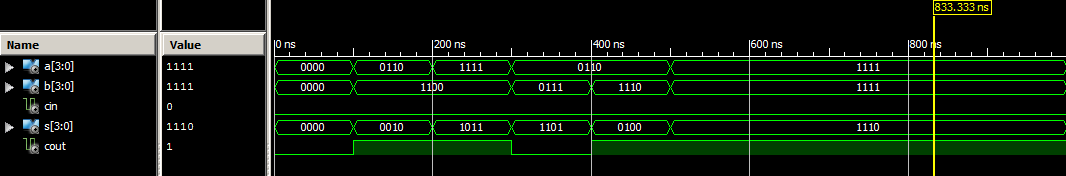
Ouput Waveform for 4-bit Ripple Carry Adder VHDL Code
Hi, when i wrote this code show me, this warning
“Warning: Positional port connection in entity/module instantiation increases the risk of design errors, affects readability, and makes your code less adaptable. Use of explicit formal/effective port connection is highly recommended instead.”
I want this clear but i can’t may be guide me
tanks so much