Table of Contents
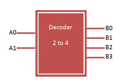
Binary decoder
Binary decoder has n-bit input lines and 2 power n output lines. It can be 2-to-4, 3-to-8 and 4-to-16 line configurations. Binary decoder can be easily constructed using basic logic gates. VHDL Code of 2 to 4 decoder can be easily implemented with structural and behavioral modelling.

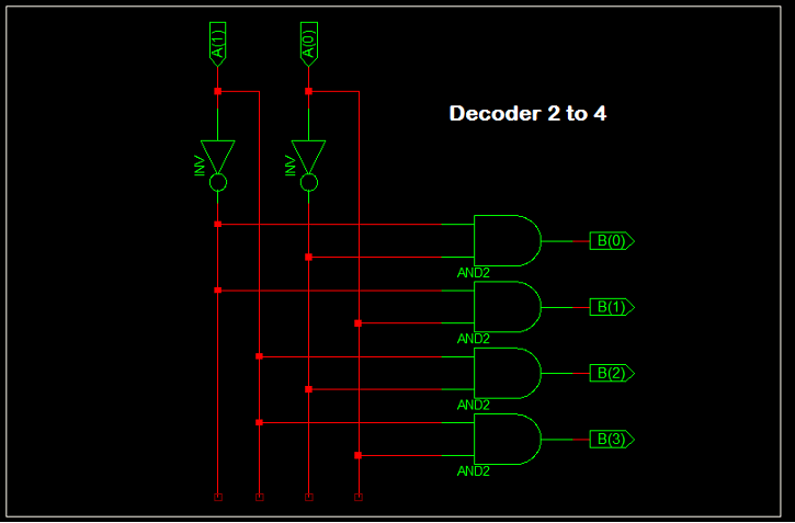
2 to 4 Decoder design using logic gates
Truth Table for 2 to 4 Decoder

Similar to Encoder Design, VHDL Code for 2 to 4 decoder can be done in different methods like using case statement, using if else statement, using logic gates etc. Here we provide example code for all 3 method for better understanding of the language.
VHDL Code for 2 to 4 decoder using case statement
library IEEE;
use IEEE.STD_LOGIC_1164.all;

entity decoder is
port(
a : in STD_LOGIC_VECTOR(1 downto 0);
b : out STD_LOGIC_VECTOR(3 downto 0)
);
end decoder;
architecture bhv of decoder is
begin

process(a)
begin
case a is
when "00" => b <= "0001"; when "01" => b <= "0010"; when "10" => b <= "0100"; when "11" => b <= "1000";
end case;
end process;

end bhv;
VHDL Code for 2 to 4 decoder using if else statement
library IEEE;
use IEEE.STD_LOGIC_1164.all;

entity decoder1 is
 port(
 a : in STD_LOGIC_VECTOR(1 downto 0);
 b : out STD_LOGIC_VECTOR(3 downto 0)
 );
end decoder1;

architecture bhv of decoder1 is
begin

process(a)
begin
 if (a="00") then
 b <= "0001";
 elsif (a="01") then
 b <= "0010";
 elsif (a="10") then
 b <= "0100";
 else
 b <= "1000";
 end if;
end process;

end bhv;
VHDL Code for 2 to 4 decoder using logic gates
library IEEE;
use IEEE.STD_LOGIC_1164.all;

entity decoder2 is
 port(
 a : in STD_LOGIC_VECTOR(1 downto 0);
 b : out STD_LOGIC_VECTOR(3 downto 0)
 );
end decoder2;

architecture bhv of decoder2 is
begin

b(0) <= not a(0) and not a(1);
b(1) <= not a(0) and a(1);
b(2) <= a(0) and not a(1);
b(3) <= a(0) and a(1);

end bhv;
TestBench VHDL Code for 2 to 4 decoder
LIBRARY ieee;
USE ieee.std_logic_1164.ALL;

ENTITY tb_decoder IS
END tb_decoder;

ARCHITECTURE behavior OF tb_decoder IS

 -- Component Declaration for the Unit Under Test (UUT)

 COMPONENT decoder
 PORT(
 a : IN std_logic_vector(1 downto 0);
 b : OUT std_logic_vector(3 downto 0)
 );
 END COMPONENT;

 --Inputs
 signal a : std_logic_vector(1 downto 0) := (others => '0');

 --Outputs
 signal b : std_logic_vector(3 downto 0);
 -- appropriate port name

BEGIN

 -- Instantiate the Unit Under Test (UUT)
 uut: decoder PORT MAP (
 a => a,
 b => b
 );

 -- Stimulus process
 stim_proc: process
 begin
 -- hold reset state for 100 ns.
 wait for 100 ns;

 a <= "00";

 wait for 100 ns;

 a <= "01";

 wait for 100 ns;

 a <= "10";

 wait for 100 ns;

 a <= "11";

 wait;
 end process;

END;
TestBench waveform for 2 to 4 decoder
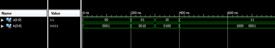
The above waveform displays the VHDL Code for 2 to 4 decoder implementation result.
I think there’s a mistake in “VHDL Code for 2 to 4 decoder using logic gates” part. In 15th and 16th rows. Lines 15 and 16 need to be moved in each other. can you check it?
Hi Yigit,
They are in right place.
A(0) represent LSB
A(1) represent MSB
add when others…. in case
here is a mistake in case stmnt ..
when “00” its ans shuld be ….”0001″ ..bt u wrote “1000” bcz acc. to binary concept 1000 is 8
Thanks for pointing out the mistake. Now it is corrected.
Nice!
You are welcome.