Table of Contents
Carry Select Adder
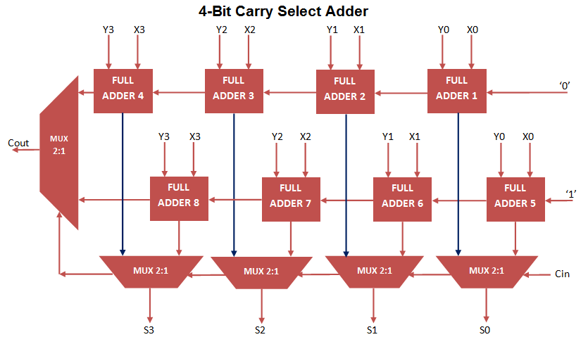
Carry Select Adder VHDL Code can be Constructed by implementing 2 stage Ripple Carry Adder and multiplexer circuit. Carry Select Adder select the sum and carry output from stage 1 ripple carry adder when carry input ‘0’ and select Sum and carry output from stage 2 ripple carry adder, when carry input ‘1’.
For the purpose of selecting sum and carry output, N+1 Multiplexer is implemented for N bit Addition Operation.
4 Bit Carry Select Adder VHDL Code consist 2 numbers of 4- bit Ripple Carry Adder and 5 numbers of 2 to 1 Mux. For constructing Ripple carry Adder again implement Full Adder VHDL code using Port Mapping technique.
The Carry select Adder can also constructed using carry look ahead adder to decrease propagation delay. 4-bit Carry Select Adder Circuit can be constructed as follow.
4-Bit Carry Select Adder Architecture
Carry Select Adder VHDL Code
library IEEE;
use IEEE.STD_LOGIC_1164.ALL;

entity carry_select_adder is
Port ( X : in STD_LOGIC_VECTOR (3 downto 0);
Y : in STD_LOGIC_VECTOR (3 downto 0);
CARRY_IN : in STD_LOGIC;
SUM : out STD_LOGIC_VECTOR (3 downto 0);
CARRY_OUT : out STD_LOGIC);
end carry_select_adder;

architecture Behavioral of carry_select_adder is

component full_adder_vhdl_code
Port ( A : in STD_LOGIC;
B : in STD_LOGIC;
Cin : in STD_LOGIC;
S : out STD_LOGIC;
Cout : out STD_LOGIC);
end component;

component mux2_1
port(
A,B : in STD_LOGIC;
Sel: in STD_LOGIC;
Z: out STD_LOGIC
);
end component;

signal A,B,C0,C1: STD_LOGIC_VECTOR( 3 DOWNTO 0);
begin

FA1: full_adder_vhdl_code PORT MAP(X(0),Y(0),'0' ,A(0),C0(0));
FA2: full_adder_vhdl_code PORT MAP(X(1),Y(1),C0(0),A(1),C0(1));
FA3: full_adder_vhdl_code PORT MAP(X(2),Y(2),C0(1),A(2),C0(2));
FA4: full_adder_vhdl_code PORT MAP(X(3),Y(3),C0(2),A(3),C0(3));

FA5: full_adder_vhdl_code PORT MAP(X(0),Y(0),'1' ,B(0),C1(0));
FA6: full_adder_vhdl_code PORT MAP(X(1),Y(1),C1(0),B(1),C1(1));
FA7: full_adder_vhdl_code PORT MAP(X(2),Y(2),C1(1),B(2),C1(2));
FA8: full_adder_vhdl_code PORT MAP(X(3),Y(3),C1(2),B(3),C1(3));

MUX1: mux2_1 PORT MAP(A(0),B(0),CARRY_IN,SUM(0));
MUX2: mux2_1 PORT MAP(A(1),B(1),CARRY_IN,SUM(1));
MUX3: mux2_1 PORT MAP(A(2),B(2),CARRY_IN,SUM(2));
MUX4: mux2_1 PORT MAP(A(3),B(3),CARRY_IN,SUM(3));

MUX5: mux2_1 PORT MAP(C0(3),C1(3),CARRY_IN,CARRY_OUT);

end Behavioral;
2 to 1 Mux VHDL Code implementation for Port Mapping in Carry Select Adder
library IEEE;
use IEEE.STD_LOGIC_1164.all;

entity mux2_1 is
port(

A,B : in STD_LOGIC;
Sel: in STD_LOGIC;
Z: out STD_LOGIC
);
end mux2_1;

architecture bhv of mux2_1 is
begin
process(A,B,Sel)
begin
if Sel = '0' then
Z <= A;
else
Z <= B;
end if;
end process;
end bhv;
Testbench VHDL Code for Carry Select Adder
LIBRARY ieee;
USE ieee.std_logic_1164.ALL;

ENTITY Tb_carry_select_adder IS
END Tb_carry_select_adder;

ARCHITECTURE behavior OF Tb_carry_select_adder IS

-- Component Declaration for the Unit Under Test (UUT)

COMPONENT carry_select_adder
PORT(
X : IN std_logic_vector(3 downto 0);
Y : IN std_logic_vector(3 downto 0);
CARRY_IN : IN std_logic;
SUM : OUT std_logic_vector(3 downto 0);
CARRY_OUT : OUT std_logic
);
END COMPONENT;

--Inputs
signal X : std_logic_vector(3 downto 0) := (others => '0');
signal Y : std_logic_vector(3 downto 0) := (others => '0');
signal CARRY_IN : std_logic := '0';

--Outputs
signal SUM : std_logic_vector(3 downto 0);
signal CARRY_OUT : std_logic;

BEGIN

-- Instantiate the Unit Under Test (UUT)
uut: carry_select_adder PORT MAP (
X => X,
Y => Y,
CARRY_IN => CARRY_IN,
SUM => SUM,
CARRY_OUT => CARRY_OUT
);

-- Stimulus process
stim_proc: process
begin
-- hold reset state for 100 ns.
wait for 100 ns;
X <= "1011";
Y <= "1111";

wait for 100 ns;
X <= "0001";
Y <= "1010";

wait for 100 ns;
X <= "0111";
Y <= "1111";
wait;
end process;

END;
Output Waveform for Carry Select Adder VHDL Code
In the above waveform, it simply perform 4 bit addition operation for input X, Y, Carry_in and Outputs Sum and Carry_out using Carry Select Adder.


