Table of Contents
Carry Save Adder
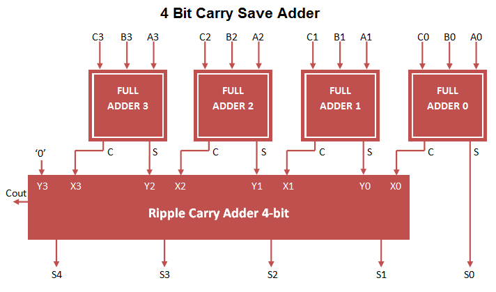
Carry save adder used to perform 3 bit addition at once. Here 3 bit input (A, B, C) is processed and converted to 2 bit output (S, C) at first stage. At first stage result carry is not propagated through addition operation. In order to generate carry, implemented ripple carry adder on stage 2 for carry propagation. Carry Save adder VHDL Code can be constructed by port mapping full adder VHDL Code to 2 stage adder circuit.
Carry Save Adder Circuit

Carry Save Adder VHDL Code
library IEEE;
use IEEE.STD_LOGIC_1164.ALL;

entity carry_save_adder is
Port ( A : in STD_LOGIC_VECTOR (3 downto 0);
B : in STD_LOGIC_VECTOR (3 downto 0);
C : in STD_LOGIC_VECTOR (3 downto 0);
S : OUT STD_LOGIC_VECTOR (4 downto 0);
Cout : OUT STD_LOGIC);
end carry_save_adder;

architecture Behavioral of carry_save_adder is

component full_adder_vhdl_code
Port ( A : in STD_LOGIC;
B : in STD_LOGIC;
Cin : in STD_LOGIC;
S : out STD_LOGIC;
Cout : out STD_LOGIC);
end component;

-- Intermediate signal
signal X,Y: STD_LOGIC_VECTOR(3 downto 0);
signal C1,C2,C3: STD_LOGIC;

begin
-- Carry save adder block
FA1: full_adder_vhdl_code PORT MAP(A(0),B(0),C(0),S(0),X(0));
FA2: full_adder_vhdl_code PORT MAP(A(1),B(1),C(1),Y(0),X(1));
FA3: full_adder_vhdl_code PORT MAP(A(2),B(2),C(2),Y(1),X(2));
FA4: full_adder_vhdl_code PORT MAP(A(3),B(3),C(3),Y(2),X(3));

-- Ripple carry adder block
FA5: full_adder_vhdl_code PORT MAP(X(0),Y(0),'0',S(1),C1);
FA6: full_adder_vhdl_code PORT MAP(X(1),Y(1),C1,S(2),C2);
FA7: full_adder_vhdl_code PORT MAP(X(2),Y(2),C2,S(3),C3);
FA8: full_adder_vhdl_code PORT MAP(X(3),'0',C3,S(4),Cout);

end Behavioral;
Testbench VHDL Code for Carry Save Adder
LIBRARY ieee;
USE ieee.std_logic_1164.ALL;

ENTITY Tb_carry_save IS
END Tb_carry_save;

ARCHITECTURE behavior OF Tb_carry_save IS

-- Component Declaration for the Unit Under Test (UUT)

COMPONENT carry_save_adder
PORT(
A : IN std_logic_vector(3 downto 0);
B : IN std_logic_vector(3 downto 0);
C : IN std_logic_vector(3 downto 0);
S : OUT std_logic_vector(4 downto 0);
Cout : OUT std_logic
);
END COMPONENT;

--Inputs
signal A : std_logic_vector(3 downto 0) := (others => '0');
signal B : std_logic_vector(3 downto 0) := (others => '0');
signal C : std_logic_vector(3 downto 0) := (others => '0');

--Outputs
signal S : std_logic_vector(4 downto 0);
signal Cout : std_logic;

BEGIN

-- Instantiate the Unit Under Test (UUT)
uut: carry_save_adder PORT MAP (
A => A,
B => B,
C => C,
S => S,
Cout => Cout
);

-- Stimulus process
stim_proc: process
begin
-- hold reset state for 100 ns.
wait for 100 ns;
A <= "1100";
B <= "1101";
C <= "1110";

wait for 100 ns;
A <= "1111";
B <= "1000";
C <= "1001";

wait for 100 ns;
A <= "1110";
B <= "0101";
C <= "0111";

wait;
end process;

END;
Output Waveform for Carry Save adder
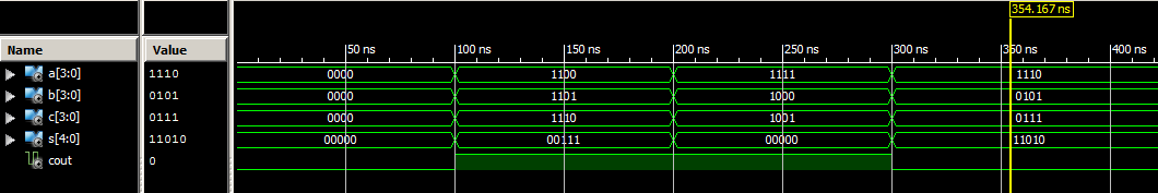
Carry Save Adder performs Addition of 3 (A, B, C) 4-bit values and output 5 bit Sum and Cout. Example result (1100 + 1101 + 1110) = 100111 (MSB Bit ‘1’ Cout , Sum 5 bit ” 00111″).