Table of Contents
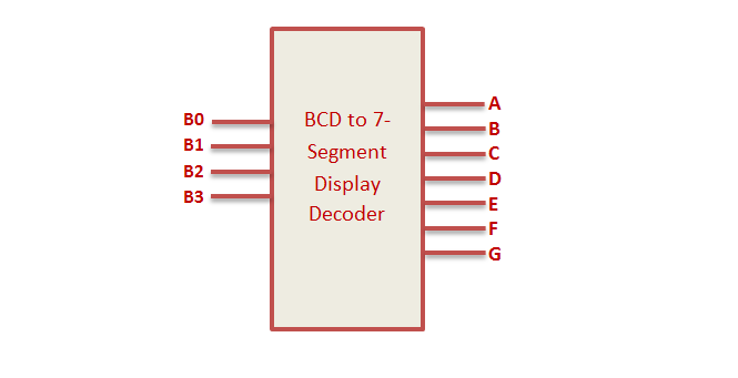
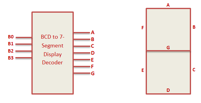
BCD to 7 Segment Decoder
The BCD to 7 Segment Decoder converts 4 bit binary to 7 bit control signal which can be displayed on 7 segment display. Seven display consist of 7 led segments to display 0 to 9 and A to F.
VHDL Code BCD to 7 Segment Display decoder can be implemented in 2 ways. By simplifying Boolean expression to implement structural design and behavioral design.
For constructing BCD to 7 segment display, first construct truth table and simplify them to Boolean expression using K Map and finally build the combinational circuit.
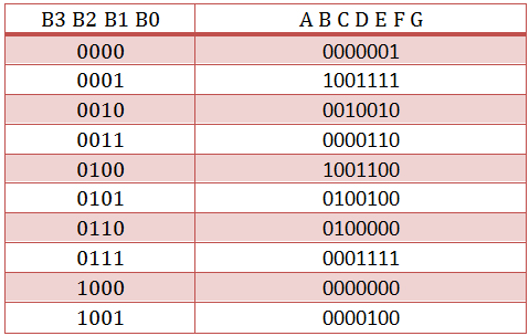
BCD to 7 segment display Decoder Truth Table
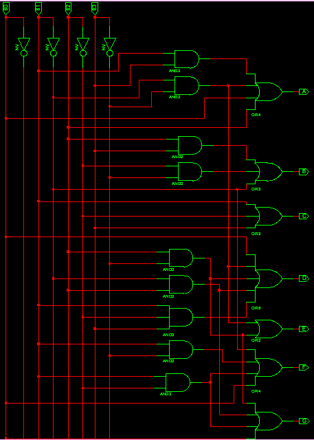
BCD to 7 segment display Decoder Circuit
The boolean expression for the logic circuit is
A = B0 + B2 + B1B3 + B1’B3′
B = B1′ + B2’B3′ + B2B3
C = B1 + B2′ + B3
D = B1’B3′ + B2B3′ + B1B2’B3 + B1’B2 + B0
E = B1’B3′ + B2B3′
F = B0 + B2’B3′ + B1B2′ + B1B3′
G = B0 + B1B2′ + B1’B2 + b2b3′
VHDL Code for BCD to 7 segment display using Combinatorial logic
library IEEE;
use IEEE.STD_LOGIC_1164.ALL;

entity bcd_7seg is
Port ( B0,B1,B2,B3 : in STD_LOGIC;
A,B,C,D,E,F,G : out STD_LOGIC);
end bcd_7seg;

architecture Behavioral of bcd_7seg is

begin

A <= B0 OR B2 OR (B1 AND B3) OR (NOT B1 AND NOT B3);
B <= (NOT B1) OR (NOT B2 AND NOT B3) OR (B2 AND B3);
C <= B1 OR NOT B2 OR B3;
D <= (NOT B1 AND NOT B3) OR (B2 AND NOT B3) OR (B1 AND NOT B2 AND B3) OR (NOT B1 AND B2) OR B0;
E <= (NOT B1 AND NOT B3) OR (B2 AND NOT B3);
F <= B0 OR (NOT B2 AND NOT B3) OR (B1 AND NOT B2) OR (B1 AND NOT B3);
G <= B0 OR (B1 AND NOT B2) OR ( NOT B1 AND B2) OR (B2 AND NOT B3);

end Behavioral;
VHDL Code for BCD to 7 segment display using Case Statement
library IEEE;
use IEEE.STD_LOGIC_1164.ALL;

entity bcd_7segment is
Port ( BCDin : in STD_LOGIC_VECTOR (3 downto 0);
Seven_Segment : out STD_LOGIC_VECTOR (6 downto 0));
end bcd_7segment;

architecture Behavioral of bcd_7segment is

begin

process(BCDin)
begin

case BCDin is
when "0000" =>
Seven_Segment <= "0000001"; ---0
when "0001" =>
Seven_Segment <= "1001111"; ---1
when "0010" =>
Seven_Segment <= "0010010"; ---2
when "0011" =>
Seven_Segment <= "0000110"; ---3
when "0100" =>
Seven_Segment <= "1001100"; ---4
when "0101" =>
Seven_Segment <= "0100100"; ---5
when "0110" =>
Seven_Segment <= "0100000"; ---6
when "0111" =>
Seven_Segment <= "0001111"; ---7
when "1000" =>
Seven_Segment <= "0000000"; ---8
when "1001" =>
Seven_Segment <= "0000100"; ---9
when others =>
Seven_Segment <= "1111111"; ---null
end case;

end process;

end Behavioral;
VHDL Testbench Code for BCD to 7 segment display
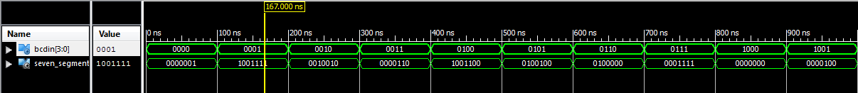
LIBRARY ieee;
USE ieee.std_logic_1164.ALL;

ENTITY tb_bcd_7seg IS
END tb_bcd_7seg;

ARCHITECTURE behavior OF tb_bcd_7seg IS

-- Component Declaration for the Unit Under Test (UUT)

COMPONENT bcd_7segment
PORT(
BCDin : IN std_logic_vector(3 downto 0);
Seven_Segment : OUT std_logic_vector(6 downto 0)
);
END COMPONENT;

--Inputs
signal BCDin : std_logic_vector(3 downto 0) := (others => '0');

--Outputs
signal Seven_Segment : std_logic_vector(6 downto 0);

BEGIN

-- Instantiate the Unit Under Test (UUT)
uut: bcd_7segment PORT MAP (
BCDin => BCDin,
Seven_Segment => Seven_Segment
);

-- Stimulus process
stim_proc: process
begin

BCDin <= "0000";
wait for 100 ns;
BCDin <= "0001";
wait for 100 ns;
BCDin <= "0010";
wait for 100 ns;
BCDin <= "0011";
wait for 100 ns;
BCDin <= "0100";
wait for 100 ns;
BCDin <= "0101";
wait for 100 ns;
BCDin <= "0110";
wait for 100 ns;
BCDin <= "0111";
wait for 100 ns;
BCDin <= "1000";
wait for 100 ns;
BCDin <= "1001";
wait for 100 ns;
end process;

END;
Testbench waveform for BCD to 7 Segment Display Decoder
Noticed a little issue with your 7 segment display circuit. The first pin on the OR4 gate for F is incorrect, you have it connected with the inverted output of B1 when it should be connected to the output of the AND2 gate located right above the connection (The AND2 gate with the inputs: Inverted B2 and Inverted B3). But other then that, I found this very useful!
Is it possible for you to link the K map simplification for a? I did for b but I keep having issues with a
Check the following link for K map simplification of BCD to 7 Segment Decoder.
https://www.electricaltechnology.org/2018/05/bcd-to-7-segment-display-decoder.html
Can you explain the boolean expressions that you got for atleast one of the segments? I have been scouring the internet because I just cant find it.
Boolean expression is the result of K MAP simplification.
According to the truth table of this 7 segment decoder, the BCD input “0” is encoded as a dash, because segment G is active. Please not that people assume high-active logic unless stated otherwise. So you should either correct your truth table and equations or state that you are using a low-active 7-segment display. Please note further, that the display itself it not low-active. The low-activeness is mostly caused by switching transistors to drive the 7-segment inputs. These transistors cause a polarity inversion.