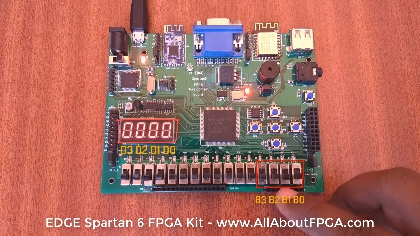
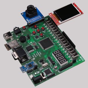
EDGE Spartan 6 FPGA Development Board consist of 16 No. of slide switches and 4 digit seven segment display. Lets display the 4 bit BCD of slide switches in the 4 digit seven segment display.
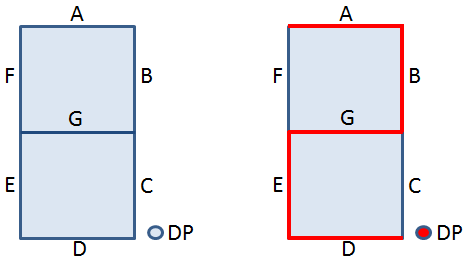
4 Digit 7 Segment Display present on edge board is common anode display.
All 4 digits can be enabled by sending logic ‘1’.
Each segment can be enabled by sending logic ‘0’
For example, lets take an 7 segment displaying 2 and dot.
Segment A, B, D, E, G, DP are enable by providing logic ‘0’ as shown in figure.
We already designed VHDL Code for BCD to Seven Segment Decoder and performed simulation of it.
Adding digit enable line to the above code outputs BCD to Seven segment Decoder realization on EDGE Spartan 6 FPGA Development Board.
library IEEE;
use IEEE.STD_LOGIC_1164.ALL;
entity bcd_7segment is
Port (
BCDin : in STD_LOGIC_VECTOR (3 downto 0);  – Slide Switch
digit : out STD_LOGIC_VECTOR (3 downto 0);        – Enable 4 digit
Seven_Segment : out STD_LOGIC_VECTOR (7 downto 0)); – 7 Segments and Dot LEDs
end bcd_7segment;
architecture Behavioral of bcd_7segment is
begin
digit <= "1111"; process(BCDin) begin
case BCDin is
when "0000" =>
Seven_Segment <= "00000011"; – -0
when "0001" =>
Seven_Segment <= "10011111"; – -1
when "0010" =>
Seven_Segment <= "00100101"; – -2
when "0011" =>
Seven_Segment <= "00001101"; – -3
when "0100" =>
Seven_Segment <= "10011001"; – -4
when "0101" =>
Seven_Segment <= "01001001"; – -5
when "0110" =>
Seven_Segment <= "01000001"; – -6
when "0111" =>
Seven_Segment <= "00011111"; – -7
when "1000" =>
Seven_Segment <= "00000001"; – -8
when "1001" =>
Seven_Segment <= "00001001"; – -9
when others =>
Seven_Segment <= "11111111"; – -null
end case;
end process;
end Behavioral;
We have assigned Switch SW2, SW4, Sw5, Sw6 for BCD input and 4 Digit seven segment display for BCD output.
FPGA Pin Details for EDGE Spartan 6 FPGA Kit
4 bit Slide Switches for Binary input
NET "BCDin[0]" LOC = P22;
NET "BCDin[1]" LOC = P21;
NET "BCDin[2]" LOC = P17;
NET "BCDin[3]" LOC = P16;
Seven segment digit selection line
NET "digit[0]" LOC = P127;
NET "digit[1]" LOC = P131;
NET "digit[2]" LOC = P132;
NET "digit[3]" LOC = P133;
Seven segment leds
NET "Seven_Segment[0]" LOC = P134;#Dp
NET "Seven_Segment[1]" LOC = P137;#G
NET "Seven_Segment[2]" LOC = P138;#F
NET "Seven_Segment[3]" LOC = P139;#E
NET "Seven_Segment[4]" LOC = P140;#D
NET "Seven_Segment[5]" LOC = P141;#C
NET "Seven_Segment[6]" LOC = P142;#B
NET "Seven_Segment[7]" LOC = P143;#A

-
 EDGE ZYNQ SoC FPGA Development Board₹ 17,500
 -
 EDGE Artix 7 FPGA Development Board₹ 13,750
 -
 EDGE Spartan 6 FPGA Development Board₹ 8,500