VHDL Code for Clock Divider (Frequency Divider)

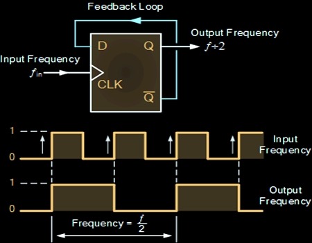
Clock Divider is also known as frequency divider, which divides the input clock frequency and produce output clock. In our case let us take input frequency as 50MHz and divide the clock frequency to generate 1KHz output signal.

VHDL code consist of Clock and Reset input, divided clock as output. Count is a signal to generate delay, Tmp signal toggle itself when the count value reaches 25000. Output produce 1KHz clock frequency.

Reference count values to generate various clock frequency output

VHDL Testbench Tutorial

VHDL Testbench Tutorial

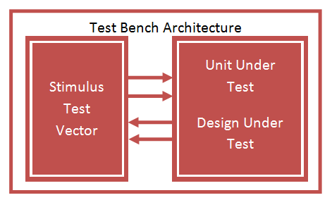
VHDL Testbench is important part of VHDL design to check the functionality of Design through simulation waveform. Testbench provide stimulus for design under test DUT or Unit Under Test UUT to check the output result.

A test bench is HDL code that allows you to provide a documented, repeatable set of stimuli that is portable across different simulators. Testbench consist of entity without any IO ports, Design instantiated as component, clock input, and various stimulus inputs.

VHDL Component and Port Map Tutorial

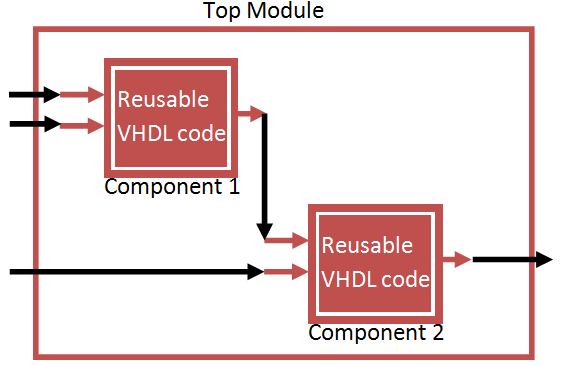
Component is a reusable VHDL module which can be declared with in another digital logic circuit using Component declaration of the VHDL Code. This helps to implement hierarchical design at ease.

Instead of coding a complex design in single VHDL Code. we can divide the code in to sub modules as component and combine them using Port Map technique.

VHDL Port Map is the Process of mapping the input/ Output Ports of Component in Main Module.

×

Chat with us for queries on the EDGE FPGA kit

×