Table of Contents
ALU
ALU’s comprise the combinational logic that implements logic operations such as AND, OR, NOT gate and arithmetic operations, such as Adder, Subtractor.
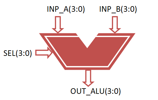
Functionally, the operation of typical ALU is represented as shown in diagram below,

Functional Description of 4-bit Arithmetic Logic Unit
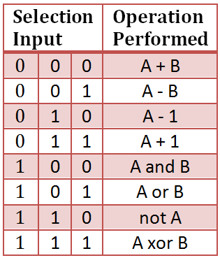
Controlled by the three function select inputs (sel 2 to 0), ALU can perform all the 8 possible logic operations
VHDL Code for 4-bit ALU
library IEEE;
use IEEE.STD_LOGIC_1164.ALL;
use IEEE.NUMERIC_STD.ALL;

entity alu is
 Port ( inp_a : in signed(3 downto 0);
 inp_b : in signed(3 downto 0);
 sel : in STD_LOGIC_VECTOR (2 downto 0);
 out_alu : out signed(3 downto 0));
end alu;

architecture Behavioral of alu is
begin
process(inp_a, inp_b, sel)
begin
case sel is
 when "000" =>
 out_alu<= inp_a + inp_b; --addition
 when "001" =>
 out_alu<= inp_a - inp_b; --subtraction
 when "010" =>
 out_alu<= inp_a - 1; --sub 1
 when "011" =>
 out_alu<= inp_a + 1; --add 1
 when "100" =>
 out_alu<= inp_a and inp_b; --AND gate
 when "101" =>
 out_alu<= inp_a or inp_b; --OR gate
 when "110" =>
 out_alu<= not inp_a ; --NOT gate
 when "111" =>
 out_alu<= inp_a xor inp_b; --XOR gate
 when others =>
 NULL;
end case;

end process;

end Behavioral;
Testbench VHDL Code for 4-Bit ALU
LIBRARY ieee;
USE ieee.std_logic_1164.ALL;
USE ieee.numeric_std.ALL;

ENTITY Tb_alu IS
END Tb_alu;

ARCHITECTURE behavior OF Tb_alu IS

 -- Component Declaration for the Unit Under Test (UUT)

 COMPONENT alu
 PORT(
 inp_a : IN signed(3 downto 0);
 inp_b : IN signed(3 downto 0);
 sel : IN std_logic_vector(2 downto 0);
 out_alu : OUT signed(3 downto 0)
 );
 END COMPONENT;


 --Inputs
 signal inp_a : signed(3 downto 0) := (others => '0');
 signal inp_b : signed(3 downto 0) := (others => '0');
 signal sel : std_logic_vector(2 downto 0) := (others => '0');

 --Outputs
 signal out_alu : signed(3 downto 0);

BEGIN

 -- Instantiate the Unit Under Test (UUT)
 uut: alu PORT MAP (
 inp_a => inp_a,
 inp_b => inp_b,
 sel => sel,
 out_alu => out_alu
 );

 -- Stimulus process
 stim_proc: process
 begin
 -- hold reset state for 100 ns.
 wait for 100 ns;

 -- insert stimulus here

 inp_a <= "1001";
 inp_b <= "1111";

 sel <= "000";
 wait for 100 ns;
 sel <= "001";
 wait for 100 ns;
 sel <= "010";
 wait for 100 ns;
 sel <= "011";
 wait for 100 ns;
 sel <= "100";
 wait for 100 ns;
 sel <= "101";
 wait for 100 ns;
 sel <= "110";
 wait for 100 ns;
 sel <= "111";
 end process;

END;
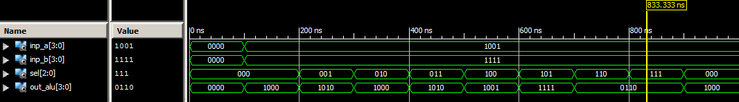
Simulation Result for 4-bit ALU
can we use for loop in testbench?
if yes then how please explain sir.
and if no then why.
Prashant, you can easily add loop in the vhdl tesh bench code
example for loop decleration
process is
begin
for i in 0 to 7 loop
wait for 100 ns;
sel <= sel + 1; end loop; end process;
what is vector here 3 down to 0 and 2 down to0
Input a and b are 4 bit vector
So 3 downtown 0
Selection line is 3 bit vector
So 2 downtown 0
Output line also 4 bit vector
So again 3 downtown 0
i am not understand the program,another method will tri sir.
Temp <= std_logic_vector((unsigned("0" & Nibble1) + unsigned(Nibble2)));
i need an explanation to the above usage of "0" & nibble1….means i want to know the clear intention of the statement…..hope i will get a response
thank you
‘0’ is concatenated with nibble because the output result give carry at MSB.
Soon, we will come up with step by step procedure to download bit in FPGA for all VHDL code and verify it.