Table of Contents
VHDL Testbench
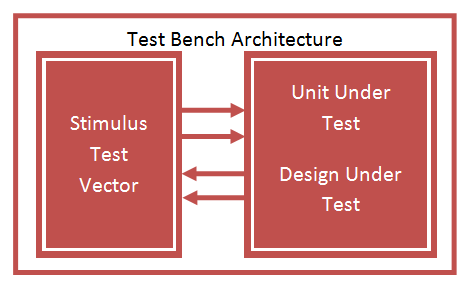
VHDL Testbench is important part of VHDL design to check the functionality of Design through simulation waveform. Testbench provide stimulus for design under test DUT or Unit Under Test UUT to check the output result.
A test bench is HDL code that allows you to provide a documented, repeatable set of stimuli that is portable across different simulators. Testbench consist of entity without any IO ports, Design instantiated as component, clock input, and various stimulus inputs.

Test Bench Syntax
ENTITY tb_name IS END tb_name;
ARCHITECTURE tb_arch OF tb_name IS
Component Declaration for the Unit Under Test (UUT)
Input/Output Signal Declaration
Clock period definitions
BEGIN
Instantiate the Unit Under Test (UUT)
Clock process definitions
Stimulus process
END tb_arch;
VHDL Testbench syntax consist of
Header File declaration containing library
LIBRARY ieee;
USE ieee.std_logic_1164.ALL;
entity without Ports declaration
ENTITY tb_up_down IS
END tb_up_down;
architecture with component declaration for unit under test
COMPONENT up_down_counter
PORT(
clock : IN std_logic;
reset : IN std_logic;
up_down : IN std_logic;
counter : OUT std_logic_vector(3 downto 0)
);
END COMPONENT;
Testbench Internal signal declaration
--Inputs signal clock : std_logic := '0';
signal reset : std_logic := '0';
signal up_down : std_logic := '0';

--Outputs
signal counter : std_logic_vector(3 downto 0);
For Sequential circuit Clock period representation for example: 50Mhz equals 20 ns.
constant clock_period : time := 20 ns;
Instantiate Design Under Test using Port Map.
uut: up_down_counter PORT MAP (
clock => clock,
reset => reset,
up_down => up_down,
counter => counter
);
Clock definition Process
clock_process :process
begin
clock <= '0';
wait for clock_period/2;
clock <= '1';
wait for clock_period/2;
end process;
Stimulus definition Process
wait for 20 ns;
reset <= '1';
wait for 20 ns;
reset <= '0';
up_down <= '0';
wait for 200 ns;
up_down <= '1';
wait;
The following VHDL Code implement the up down counter,next code implement VHDL Testbench for up down counter and finally testbench waveform output.
Testbench Example: VHDL Code for Up Down Binary Counter
library ieee;
use ieee.std_logic_1164.all;
use ieee.std_logic_unsigned.all;

entity up_down_counter is
port( clock : in std_logic;
reset : in std_logic;
up_down : in std_logic;
counter : out std_logic_vector(3 downto 0));
end up_down_counter;

architecture bhv of up_down_counter is
signal t_count: std_logic_vector(3 downto 0);
begin
process (clock, reset)
begin
if (reset='1') then
t_count <= "0000";
elsif rising_edge(clock) then
if up_down = '0' then
t_count <= t_count + 1;
else
t_count <= t_count - 1;
end if;
end if;
end process;

counter <= t_count;
end bhv;
VHDL Testbench code for up down binary counter
LIBRARY ieee;
USE ieee.std_logic_1164.ALL;

-- Uncomment the following library declaration if using
-- arithmetic functions with Signed or Unsigned values
--USE ieee.numeric_std.ALL;

ENTITY tb_up_down IS
END tb_up_down;

ARCHITECTURE behavior OF tb_up_down IS

-- Component Declaration for the Unit Under Test (UUT)

COMPONENT up_down_counter
PORT(
clock : IN std_logic;
reset : IN std_logic;
up_down : IN std_logic;
counter : OUT std_logic_vector(3 downto 0)
);
END COMPONENT;

--Inputs
signal clock : std_logic := '0';
signal reset : std_logic := '0';
signal up_down : std_logic := '0';

--Outputs
signal counter : std_logic_vector(3 downto 0);

-- Clock period definitions
constant clock_period : time := 20 ns;

BEGIN

-- Instantiate the Unit Under Test (UUT)
uut: up_down_counter PORT MAP (
clock => clock,
reset => reset,
up_down => up_down,
counter => counter
);

-- Clock process definitions
clock_process :process
begin
clock <= '0';
wait for clock_period/2;
clock <= '1';
wait for clock_period/2;
end process;

-- Stimulus process
stim_proc: process
begin
-- hold reset state for 100 ns.
wait for 20 ns;
reset <= '1';
wait for 20 ns;
reset <= '0';
up_down <= '0';
wait for 200 ns;
up_down <= '1';
wait;
end process;

END;
Testbench Waveform for Up Down Binary Counter
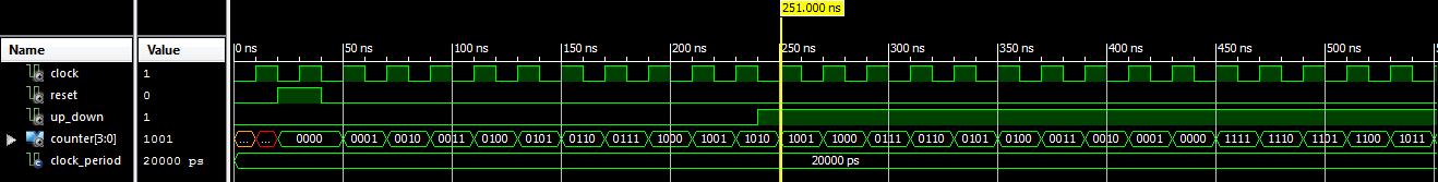
In the above waveform the counter output is “UUUU” for 10 ns at clock low period, “XXXX” for next 10 ns at clock High period. After that reset is HIGH for 20 ns so counter outputs “0000”, then Counter start up counting for 200 ns and down count for remaining time period.
Nice explanation, although you should give a different names for component signals and local architecture signals. For example “clock=>clock” rise question (newbies like me) what clock at left side and what at right side.