Table of Contents
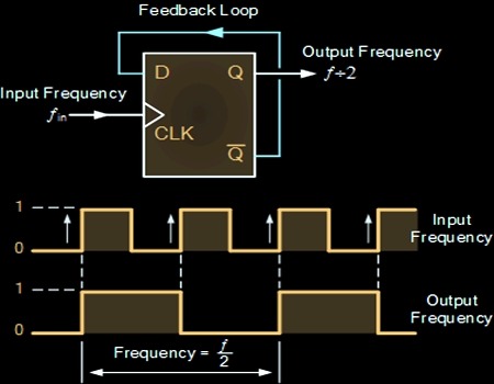
Clock Divider
Clock Divider is also known as frequency divider, which divides the input clock frequency and produce output clock. In our case let us take input frequency as 50MHz and divide the clock frequency to generate 1KHz output signal.
VHDL code consist of Clock and Reset input, divided clock as output. Count is a signal to generate delay, Tmp signal toggle itself when the count value reaches 25000. Output produce 1KHz clock frequency.
Reference count values to generate various clock frequency output
Count Value Output Frequency
1 25MHz
25 1MHz
50 500KHz
1000 25KHz
25000000 1Hz
VHDL Code for Clock Divider
library IEEE;
use IEEE.STD_LOGIC_1164.ALL;
use IEEE.numeric_std.ALL;

entity Clock_Divider is
port ( clk,reset: in std_logic;
clock_out: out std_logic);
end Clock_Divider;

architecture bhv of Clock_Divider is

signal count: integer:=1;
signal tmp : std_logic := '0';

begin

process(clk,reset)
begin
if(reset='1') then
count<=1;
tmp<='0';
elsif(clk'event and clk='1') then
count <=count+1;
if (count = 25000) then
tmp <= NOT tmp;
count <= 1;
end if;
end if;
clock_out <= tmp;
end process;

end bhv;
VHDL Testbench code for Clock Divider
LIBRARY ieee;
USE ieee.std_logic_1164.ALL;

ENTITY Tb_clock_divider IS
END Tb_clock_divider;

ARCHITECTURE behavior OF Tb_clock_divider IS

-- Component Declaration for the Unit Under Test (UUT)

COMPONENT Clock_Divider
PORT(
clk : IN std_logic;
reset : IN std_logic;
clock_out : OUT std_logic
);
END COMPONENT;

--Inputs
signal clk : std_logic := '0';
signal reset : std_logic := '0';

--Outputs
signal clock_out : std_logic;

-- Clock period definitions
constant clk_period : time := 20 ns;

BEGIN

-- Instantiate the Unit Under Test (UUT)
uut: Clock_Divider PORT MAP (
clk => clk,
reset => reset,
clock_out => clock_out
);

-- Clock process definitions
clk_process :process
begin
clk <= '0';
wait for clk_period/2;
clk <= '1';
wait for clk_period/2;
end process;

-- Stimulus process
stim_proc: process
begin
wait for 100 ns;
reset <= '1';
wait for 100 ns;
reset <= '0';
wait;
end process;

END;
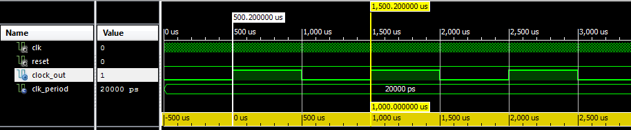
Testbench Waveform for 1Khz Clock divider from 50MHz clock input
what if I have a 100Mhz fpga
I tried the same but i took Count signal as 2 downto 0 and gave my out as Out <= cnt(2) the third bit of cnt but it isn't generating any output then tried by directly giving out <= cnt then to no output.. why??
But how to make a asynchronous reset?
I think it should be
end process;
clock_out <= tmp;
end bhv;
Instead of
clock_out <= tmp;
end process;
end bhv;
Since tmp is a signal
hi..
I have 40 Hz clock for my program.. but it is required to send data at a rate of 10 us pulse within 2 second time interval.. I have also convert 40 Hz pulse into 2 second. please guide me how to send data at a rate of 10 usec.?
helo, first i want say thank you for giving me this,
but i want to ask you several things:
1. is it possible to make it become single trigger signal ?
2. and is it possible to register it in FPGA I/O, so that i can check the wave from my osciloscope
thank you ^^
Why did not you use the variable instead of using the signal for the counter?
signals are global. variable are local to the process. signals can used in multiple process statements.
I want do divide 1GHz to 33 using your method. How would I have to change the code above?
Hi, i want my clock divide by integer. Like 10, 20 etc. (5MHz, 2.5 MHz) How can i do that? Could you help me?
for divider by 10, 20, 30
You change the count value by 5, 10, 15. so output will be 5MHz, 2.5MHz, 1.667MHz and so on…
Thanks 🙂 One more thing. If i want divide by 5, so 10Mhz, how should i change the count?
How do you calculate output clock frequency, teach me.
If I want clock out to be 25 MHz, how do I set count=?
Refer the table above. For 25 Mhz, count value should be 1.
But if count = 1 then the output clock will equal input clock if count value initialized by one
so we need to initialized it by zero
signal count: integer:=1;
if(reset=’1′) then
count<=0;
tmp<='0';
if (count = 1) then
tmp <= NOT tmp;
count <= 0;
end if;
Your counter does not provide a 1kHz output signal, because it counts 25,001 cycles (0 .. 25k equals 25,001).
Regards
Patrick
Thanks, Now updated as 1 to 25k instead of starting from 0.
Rafer the following post for How to create VHDL Testbench?
http://allaboutfpga.com/vhdl-testbench-tutorial/
You need to toggle reset from high to low after some delay in testbench code.
I will update the code with testbench soon.
how do i generate the vhdl test bench code??for the above program…
Updated with testbench code for the clock divider
Pls suggest me program for output y =1 when s=1 for continuous 3 clock pulse… If S changes btwn 3 clk pulse then output should goes low… Sequential circuit
Rakshith, try the following declare count as integer
if s= ‘1’ then
count = count + 1;
if count = 3 then
count = 0;
y = ‘1’;
end if;
else
y = ‘0’;
count = 0;
end if;
Hi, i was trying to use your clock, but it keeps sending the error of ‘counter’ not being assigned, any ideas on how to fix it?
Error (10482): VHDL error at Clock_divider.vhd(24): object “counter” is used but not declared
I’ve fixed that, sorry, just a typo, was trying to divide it down to 1MHz using
‘ if (counter = (25/10000))’
but so far it only goes as far as 500kHz :/
Use count instead of counter
Output can’t be inverted directly and assign to the same output port.. That’s why declared tmp signal and finally assigned to output.
Why we need tmp signal instead of directly inverting clkout?